The STM32Cube MX is great for checking what inputs and outputs are possible with a given chip.
The recording and playback software example are a good start.
Think the CMSIS-DSP Algorithms, C functions are quite easy to use and well documented.
(Easy is maybe not right, compact code is more correct🙂
The recording and playback software example are a good start.
Think the CMSIS-DSP Algorithms, C functions are quite easy to use and well documented.
(Easy is maybe not right, compact code is more correct🙂
Last edited:
Some more about audio input/output on F446:
Say 7xi2s ???
1xspdif (like you say torgeirs)
2xSAI ????
https://my.st.com/public/STe2ecommunities/mcu/Lists/cortex_mx_stm32/Flat.aspx?RootFolder=https%3a%2f%2fmy.st.com%2fpublic%2fSTe2ecommunities%2fmcu%2fLists%2fcortex_mx_stm32%2fSTM32F446%20Widen%20Access%20to%20High-Performance%20Line%20with%20Small%20Memory&FolderCTID=0x01200200770978C69A1141439FE559EB459D7580009C4E14902C3CDE46A77F0FFD06506F5B¤tviews=630
Last edited:
Some example for input/output i2s with bufering isue solved:
https://my.st.com/public/STe2ecommu...14902C3CDE46A77F0FFD06506F5B¤tviews=607
https://my.st.com/public/STe2ecommu...14902C3CDE46A77F0FFD06506F5B¤tviews=607
Some more about audio input/output on F446:
Say 7xi2s ???
1xspdif (like you say torgeirs)
2xSAI ????
Think they specs the functions as or, not and🙂
And with the nucleo they use 64 pin chips so there are still more overlap on pins between the functions.
Still there are a lot of posibilities.

Some example for input/output i2s with bufering isue solved:
https://my.st.com/public/STe2ecommu...14902C3CDE46A77F0FFD06506F5B¤tviews=607
I also hope ST will release some code when the amp gets to market.
My HOPE is that they make code to the board that is "turn key" SPDIF to I2S. So that one can download code and play on the amps with SPDIF in.
I suspect it will maybe only be USB or I2S in.
But reading the STM32 forum you directed to, I see there are a lot of people interested in this. So i hope somone will release som nice code.
I think as there are code that can send data from SPDIF to I2S, there should be no problem grabbing these data from memory and run DSP functions on them.
Transforming from I2S to TDM/PCM should also be pretty straightforward using CubeMX as guide.
Last edited:
So i hope somone will release som nice code.
So have you looked at Audio Weaver, does it have ASRC implementation? If yes is then how many MIPS it takes to process like a stereo channel?
By someone I mean ST, students, universities or enthusiasts.
Like:
Christoph's Homepage - Realtime-Audio-DSP Tutorial with the ARM STM32F4-Discovery Board
Realtime Audio DSP with the STM32F4
https://community.arm.com/thread/6086
ARM Cortex-M CMSIS Library Support from DSP System Toolbox ? Hardware Support - MathWorks Nordic
ARM Introduces DSP ‘Lab-in-a-Box’ For Education Combining STMicro STM32F4-Discovery Board and Wolfson Audio Card
Using the S/PDIF block as input for processing in STM32F446 definitely requires arbitrary sampling rate conversion. This paper discusses the DSP algorithms and implementation alternatives and presents one such:
http://www.dspconcepts.com/sites/default/files/white-papers/Beckmann Stilson AES2005_ASRC.pdf
It says the algorithm takes max. 13.5 MIPS on SHARC DSP. Beckmann (the other author) has later estimated that the performance on Cortex-M4 is roughly 5 times slower for FIR (0.21 exactly), so the ASRC takes about 65 MIPS on M4(F), see this paper:
http://www.dspconcepts.com/sites/default/files/white-papers/PD8_Beckmann.pdf
Now I assume that the Audio Weaver ASRC is developed by Beckmann himself, so you might want to ask him if you have any questions, his email address is told at the last page of the paper.
Regarding the timer counter it can be useful in implementation of ASRC as it can be used to calculate the instant sampling rate ration of SPDIF input and I2S/TDM output (though it can be also calculated also using the circular DMA interrupts/callbacks).
Using the Audio Weaver example in the latter paper the speaker crossover is estimated taking 63.16 MIPS on Cortex-M4, so the total ASRC + XOVER takes about 130 MIPS which in my opinion is too much required for STM32F446 running at 180 MHz (when you add wait states, interrupt latencies and such you cannot execute 130 million instructions / second).
However, if your S/PDIF source is synchronous to STM32 chip running as clock master then it is possible to use the S/PDIF input. Many professional audio interfaces (ans some semi-pro) have either WordClock or SuperClock input or can synchronize to external S/PDIF signal.
On the other hand Beckmann claims that SRC takes only 10% of Cortex-M4 resources:
http://www.dspconcepts.com/sites/default/files/white-papers/STM32Journal_DSPC.pdf
Anyway, the audio Weaver Cortex-M4 ASRC is not freeware.
http://www.dspconcepts.com/sites/default/files/white-papers/STM32Journal_DSPC.pdf
Anyway, the audio Weaver Cortex-M4 ASRC is not freeware.
Atmel SAM V Cortex-M7 series can run at 300 Mhz, would sure be better platform for audio DSP than STM32F4:
SAM V MCUs
SAM V MCUs
ST too have M7 Cortex ARM MCU (running at 216MHZ) for a few moths with a discovery kit (eval board) for only a 55$ buck board with display attached.
I think even better than ATMEL...but i dont know ATMEL enough.
http://www.st.com/web/catalog/tools/FM116/SC959/SS1532/LN1848/PF261641#
I think even better than ATMEL...but i dont know ATMEL enough.
http://www.st.com/web/catalog/tools/FM116/SC959/SS1532/LN1848/PF261641#
Using the S/PDIF block as input for processing in STM32F446 definitely requires arbitrary sampling rate conversion.
Could you explain more in detail why?
I don't understand why the input SPDIF samplerate can not be replicated with the ST clocks, measurung the spdifrx_frame_sync with timers.
A table of values for audioPLL and small increments of masterclock frequencys should be possible to make.
The other case is if some student make a ASRC with -90dB noise (following the signal) , light footprint and makes it public. Maybe it is good enough....
I too don't understand what mhelin say means...but im not the person what can debate this.
Anyway I found a example working spdif (and usb) audio input not in SM32F446 but in STM32F7.
Not seems so much trouble to make it working properly and you can download and see the code. For me seems very suitable to all STM32 boards.
STM32F7 Discovery Sound Card
Regards
Anyway I found a example working spdif (and usb) audio input not in SM32F446 but in STM32F7.
Not seems so much trouble to make it working properly and you can download and see the code. For me seems very suitable to all STM32 boards.
STM32F7 Discovery Sound Card
Regards
Last edited:
I too don't understand what mhelin say means...but im not the person what can debate this.
Anyway I found a example working spdif (and usb) audio input not in SM32F446 but in STM32F7.
Not seems so much trouble to make it working properly and you can download and see the code. For me seems very suitable to all STM32 boards.
STM32F7 Discovery Sound Card
Regards
There are no attempts made to synchronize the streams. The implementation just sends out (using DMA transfer) the data that is received by SPDIF (interrupt driven).
If there is a large buffer (above uses 15360 samples buffer) and it happens that the SPDIF source has just a little bit faster clock so it produces let's say just a single sample per second more than is consumed (by I2S sender) you will not notice anything very soon. 1 sample / sec means 3600 samples in an hour. If you software monitors the difference of the system clocks then it could in the opposite case (receiver side is slower) just delay the start of playback for a little time to fill the buffer to avoid underflow.
For realtime use you should write tighter processing loop with say 128 samples or even less (32 samples should be fine on these devices). Assume you are a musician and want to use software realtime synthesizer plugins in your DAW app. You want the input be processed to output ASAP. 10 ms latency is maximum, for the whole system.
For realtime use you should write tighter processing loop with say 128 samples or even less (32 samples should be fine on these devices). Assume you are a musician and want to use software realtime synthesizer plugins in your DAW app. You want the input be processed to output ASAP. 10 ms latency is maximum, for the whole system.
Last edited:
If there is a large buffer (above uses 15360 samples buffer) and it happens that the SPDIF source has just a little bit faster clock so it produces let's say just a single sample per second more than is consumed (by I2S sender) you will not notice anything very soon. 1 sample / sec means 3600 samples in an hour. If you software monitors the difference of the system clocks then it could in the opposite case (receiver side is slower) just delay the start of playback for a little time to fill the buffer to avoid underflow.
For realtime use you should write tighter processing loop with say 128 samples or even less (32 samples should be fine on these devices). Assume you are a musician and want to use software realtime synthesizer plugins in your DAW app. You want the input be processed to output ASAP. 10 ms latency is maximum, for the whole system.
I understand that in some cases (like that musician you say) is needed a propper sync from input to output but not to any "real-time" application.
If not hear (or need have some kind feedback) from source you can live with the little (in human terms) delay of processing audio from the source origin to the speakers.
I still dont understand why need (to our purposses that only make dsp process to an audio streming source) some sort of sync about inputs (spdif, SAI, etc...) to output.
Any delay (some ms) from source streaming audio will be aceptable because we only "hear" the last stage (speaker) at the end...but maybe im keep missing something.
I only can understand that we need keep well synced input with the source streaming device "origin" with all our audio process (input buffering, dsp process, full out buffering) and then mantain (with the output buffering) streaming output synced with the "consumer" device.
Regards
Last edited:
Before I forget mention that the tricky thing here is have a really good procesing buffering with enough lengths and all the resources for they can mantain stable a well sync in both streaming paths in and out. But i'm sure there are a well know method for do that and knowing everyone know ST32M4 audio projects.
Maybe someone in DSPconcepts can help to point that on route...
Maybe someone in DSPconcepts can help to point that on route...
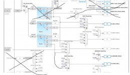
Regarding SPDIF sync:
Input frequency of SPDIF in can be measured by the spdifrx_frame_sync and timers. Then the clock can be set for the same output frequency.
Measuring for 0.1 second gives quite accurate value.
Then the output masterclock frequency can be set and output turned on.
The audiostream don't have to be delayed, just muted for the first 0.1 second.
The picture shows thet there are quite som divisions that can give a almost exact mach of frequencies. In addition samples can be replicated on zero crossing when needed.
Attachments
- Home
- Source & Line
- Digital Line Level
- STM 32 F4 Discovery and Audioweaver, anyone tried?