The measurements are very different depending on the leakage inductance (especially) of the transformer. But seeing the length of ringing increase with an added snubber is unusual, at least IME.
I suspect that the leakage inductance of your trafo is lower than usual - no bad thing.
In your first posts, the expanded view of the turn-ON pulses showed several cycles of ringing - is that still so?
Other checks:
- are the wires between trafo -> rectifier -> C1 short (<100mm/4") ?
- If you have values of suitable C1 below 1uF, they may be worth experimenting. C1 is used to prevent over-large voltage swings across the choke. I like to use PSUD2 to model the supply, and have the minimum repetitive voltage come in at around 10% of the dc output voltage. This makes for almost all of the wide conduction-angle advantages of a choke-input supply, but with minimised voltage stress on the choke. The lowest value of C1 that achieves this(at the normal dc load current) is likely to be best. And a reduced C1 will reduce the amplitude of the pulses.
The wires between transformer and rectifier are much longer - at least 20cm. It's a prototype of an amp that I am experimenting with. I was hoping to see a quick result, but it seems that I should wait with the power details until I do a final build - I will use a different transformer too. Will research the PSU2D, thank you for sharing.
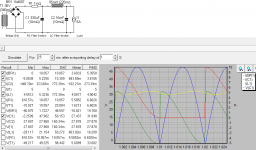
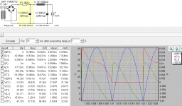
Regarding the ringing, it depends on what pulse you mean. I see 3 different pulses in the image below (with ISL9R8120P2). The very first pulse with clear ringing - this ringing is significantly smaller with UF4007 (third image below). The second - sharp pulse with the high amplitude (see second image below for details) is still there. A smaller version of this pulse shows up when I turn filament power on and before I turn on this transformer. And the third pulse, that follows the second pulse on the image below probably got a bit worse with UF4007. I understand that the first pulse is when diodes open and close. I do not understand what other two pulses are.


Regarding the ringing, it depends on what pulse you mean. I see 3 different pulses in the image below (with ISL9R8120P2). The very first pulse with clear ringing - this ringing is significantly smaller with UF4007 (third image below). The second - sharp pulse with the high amplitude (see second image below for details) is still there. A smaller version of this pulse shows up when I turn filament power on and before I turn on this transformer. And the third pulse, that follows the second pulse on the image below probably got a bit worse with UF4007. I understand that the first pulse is when diodes open and close. I do not understand what other two pulses are.
Last edited:
The 1uF cap before the choke brought up the final DC voltage from 400V to 480V! I think it should also bring requirements for the choke and the large cap down a lot!
If this type of supply is used with high current (say, 24Vdc @ 5A), is there call to use solenoid style beads?
Scroll down to 10th June 2015 update and you can see my measurements from about the same experiments with 1N vs UF diodes. I have not yet tried adding ceramic snubber capacitors to catch the tiny little rest of switching noise.
100W 6P45S monoblock tube amplifier | Kaizer Power Electronics
100W 6P45S monoblock tube amplifier | Kaizer Power Electronics
MadKaizer, very nice amp project! I bet it sounds awesome! I use star ground. Tried it with an input connected to a source and disconnected with the same result, so ground loop is not likely. I was also thinking of ceramic snubber caps.
The 1uF cap before the choke brought up the final DC voltage from 400V to 480V! I think it should also bring requirements for the choke and the large cap down a lot!
1uF is too high, if the voltage rises so much. It means that the conduction angle is dropping toward Cap-input filter levels. The regulation of the supply will be degraded, and the EM emissions worse.
PSUD2 will make it easy to diagnose. It's a function of dc load current, and all the other component parameters. Try reduced values of C1 until the voltage levels off back near to 400V.
This should also reduce the amplitude of your measured pulses.
It looks like some of the pulses are negative - is the current-sniffing toroid looped onto the wire from bridge to C1 (not on one of the diode leads)?
The UF4007 helps with its lower pulse amplitudes, and with a lower C1 we can reduce them further.
Rod, I'm having trouble understanding your use of a smallish C1, 1uf, in front of L3. I understand the reasoning of using it to squelch noise, but I can't help but think it might just be better to use a largish, 100-220uf there. Morgan Jones has pointed out, and it shows up in PSUD, that if you use a 1 through 10uf cap there you will change the output voltage progressively. One can actually mold the output voltage through that means fairly smoothly from an inductor input voltage, .9 of computed transformer output, to a capacitor input voltage, i.e. 1.41 of transformer output.
This comes at a cost though. The power supply impedance can more than double over an inductor input power as it moves through that range. This can cause all sorts of problems. That includes possible low frequency motorboating due to feedback through that high impedance power supply. Also, if you change the current consumption through the amp, for whatever reason, you are likely to get a changing power supply voltage.
Perhaps I'm missing something. If I am, then my apologies. But wouldn't it just be better on the whole to get the appropriatly rated power transformer and just use a CLC filter with a large input C. You would still have to make the concessions for squelching the large inrush current into it. PSUD shows good results using that approach.
I should probably clarify the drawing when I get a minute - the 1uF may be too high for many combinations of (low)dc load and (low)trafo winding resistance. My intention is to show a choke-input supply.
The choke-input supply with a small cap (the value depends on the range of load currents, and the dc resistance in the trafo secondary) maintains the virtues of a choke-input supply, which all stem from the wide conduction angle. This allows the peak current to reduce in magnitude, and spread out over a longer interval. This in turn reduces the rms value of the trafo current (meaning: lower stress on everything, especially rectifiers and trafo, and thus lower heat generation).
The lower current peaks also mean lower emitted magnetic field arising from the rectifier pulses - which may couple into the signal parts of an amp.
Lastly, the choke-input filter regulates better (lower voltage drop for increase in dc load current).
The cap C1 is only to prevent extremes of voltage swing across the choke.
So yes, you can build a cap-input supply with 100uF C1, but this will run more stressfully, and generate larger EM emissions, and usually, more conducted noise as well. Especially if you are building with a single chassis, where noise coupling is harder to prevent, this is a serious consideration.
Yes, according MJ's chart in his book, the demarcation for a changing power supply impedance is 0.7 uf. So a .5 uf capacitor for C1 should be a good safe value for your purposes.
One thing I often get confused about is how inductors are rated for current. There's not much talk that I see about how it changes with ripple current vs total current. I understand that a magnetic field is built up in iron surrounding a coil regardless of whether the current is direct or alternating in the coil. So the iron can be saturated with flux regardless and then not respond to changes in current.
But wouldn't it be true that if you could minimize the ripple current riding on top of the direct current that you might be able to downsize the inductor significantly. It seems like what would have to happen in that situation is that you have a gapped inductor, just like SE output transformers. It seems to me that CLC filter "could" have significant advantages over an LC filter in such a case. Rod, do you or anyone else, know if there's been a study or discussion of use of such a swinging choke in a CLC filter. Also, how small and cheap could one actually get that gapped choke to be compared to a normal choke in an LC filter application. Inquiring minds want to know.
I just realized those last two paragraphs of my last post are a bit off topic to this subject. If the forum gods think this subject is worthy of a separate thread I don't mind if they move it. Either way works for me.
Yes, according MJ's chart in his book, the demarcation for a changing power supply impedance is 0.7 uf. So a .5 uf capacitor for C1 should be a good safe value for your purposes.
One thing I often get confused about is how inductors are rated for current. There's not much talk that I see about how it changes with ripple current vs total current. I understand that a magnetic field is built up in iron surrounding a coil regardless of whether the current is direct or alternating in the coil. So the iron can be saturated with flux regardless and then not respond to changes in current.
But wouldn't it be true that if you could minimize the ripple current riding on top of the direct current that you might be able to downsize the inductor significantly. It seems like what would have to happen in that situation is that you have a gapped inductor, just like SE output transformers. It seems to me that CLC filter "could" have significant advantages over an LC filter in such a case. Rod, do you or anyone else, know if there's been a study or discussion of use of such a swinging choke in a CLC filter. Also, how small and cheap could one actually get that gapped choke to be compared to a normal choke in an LC filter application. Inquiring minds want to know.
Hi - The choke must be rated to handle the peak current encountered in the application. In practice, the inductance value of a real choke reduces as the current increases (e.g. Hammond 153 outline data):
Hammond Mfg. - D.C. Filter Chokes - (153 - 159 Series)
So we are choosing a choke based on the expected amount of filtering (L value) for a given current waveform.
When choosing between Cap- and Choke-input, though - there is little difference in the peak current carried in the choke, in each case. (Assuming the inductance value is sufficient).
Try it in PSUD2 - select "IL1" to view the current waveform.
With HV supplies, there is a difference in the voltage differential, and care must be taken that a choke is suitable for choke-input duty at the voltages found in the circuit.
I always prefer a choke input supply, for all the reasons listed in earlier post above, stemming from the wide conduction angle.
Rod, thank you so much for helping! The current transformer is between the PT and rectifier. Changed C1 to 0.1uF - voltage dropped back 400V. However I still get the cleanest waveform without C1 and RC (image below) and I tried combinations from 10n to 100n with resistors from 100Ohm to 1k.

Rod, I'm a little confused by your reference to a wide conduction angle. Maybe you can elaborate. I'm conversant with voltage leading current in inductors (I hope I didn't reverse that)and how it varies with the reactance of the inductance in combination the straight resistance of the circuit it's feeding.
What I was referring to about the current rating of inductors was this: In a regular inductor you have to size the iron for the direct current moving through the coil, regardless of the size of the ripple riding on top of it. Also the coil has to be rated for the voltage applied. This tends to make a power supply bulky and inefficient when using an inductor to correct small ripple currents riding on high direct current levels as in a typical tube HT power supply. So there is no advantage to using a CLC filter in that situation. What I'm saying is divorced from the good argument you bring up of the performance advantages of a LC power supply filter.
But it seems there might be a way of creating a more justifiable use of a CLC filter if you could size the inductor for the size of the ripple current riding on top of the direct current. A ferrite bead inductor is just a gapped inductor where there is a practically infinite number of gaps. So, the gapped iron idea can really be thought of as a "spectrum" ranging from 1 gap for SE output transformers right up ferrite beads.
It seems like there should be a way to create inductors in an intermediate number of gaps in the iron so that you could create an inductor that is relatively physically small but still has high direct current capacity and has a high henry value that is able to tame the small ripple voltages involved in a CLC power supply filter. I'm not saying they are out there. And it is also divorced from the good argument you supplied for an inductor input filter. I just think inductors work great for taming ripple. Much better than capacitors only. It seems like it would be a useful implementation.
Forgive me for getting too theoretical here. You are really supplying a lot of great hands on info here that I really appreciate. What you have been saying in this thread makes so much sense that it actually inspires these kinds of more general and theoretical questions.
Last edited:
Actually, I think I just figured out what you meant by a wide conduction angle. You must've meant the rectifying diodes have a long conduction time in each cycle in an LC filter versus a CLC filter. I guess that's because there's no input capacitor to get topped up and whose voltage must be overcome before current flows. Very good point that I hadn't really considered.
Thanks for pointing this out. I've been seeing ferrite as a method to deal with eddy currents. This answers my previous question.A ferrite bead inductor is just a gapped inductor where there is a practically infinite number of gaps.
I've changed my bass amp supply to CLC to increase the voltage. I didn't have a suitable toroid on hand but I had the chokes. They are quite out of proportion to look at.bulky and inefficient when using an inductor to correct small ripple currents riding on high direct current levels
On the other hand when it was cLC, I used an old power transformer (at first) as the choke, and it worked.
..
Hoping this would be helpful, here is a screen shot of a supply. Of note I think is that the inductor current remains positive, the first capacitor current is smooth and continuous and the diode conducts until the end of the half cycle.
Attachments
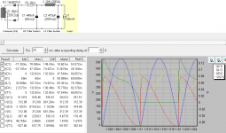
Rod, thank you so much for helping! The current transformer is between the PT and rectifier. Changed C1 to 0.1uF - voltage dropped back 400V. However I still get the cleanest waveform without C1 and RC (image below) and I tried combinations from 10n to 100n with resistors from 100Ohm to 1k.
Yes, it is looking fairly clean already in that waveform. Does the transformer have a low value of winding resistance? like < 10 ohm? It may help to add a little resistance between the rectifier and C1, if you have any suitable values around. Maybe 5-10 ohm 10W wirewound. This will help to damp the current "twang" in the transformer.
Or, if the sniffed current-waveform remains better without the snubber, try even lower values of C in the snubber. Even 470p may help, in this case.
Actually, I think I just figured out what you meant by a wide conduction angle. You must've meant the rectifying diodes have a long conduction time in each cycle in an LC filter versus a CLC filter. I guess that's because there's no input capacitor to get topped up and whose voltage must be overcome before current flows. Very good point that I hadn't really considered.
Yes, that is exactly the meaning. It is the diode ON-time, effectively. Since the mains waveform is a sinusoid - IOW a circular function - it is usual to talk about portions (or fractions) of it in terms of angle.
So for example, for the 360 degrees of mains sine wave, there are two positive pulses (full wave rectifier turns the negative half-cycle into a positive one).
A Cap-input filter's rectifier might conduct only one third of the time (120 degree) - where a properly-optimised choke input filter will conduct continuously (360 degree).
<cut>
..
Hoping this would be helpful, here is a screen shot of a supply. Of note I think is that the inductor current remains positive, the first capacitor current is smooth and continuous and the diode conducts until the end of the half cycle.
Yes, that's a perfect example.
The added R before C1 is often needed, if the trafo winding resistance is low.
Thanks Rod, I'm pleased with the results.. Here also is the first stage of a low current bias supply, and a solid state supply to show how versatile I find this circuit (I've built them all, as well as a bipolar SS supply).
Attachments
- Status
- Not open for further replies.
- Home
- Amplifiers
- Tubes / Valves
- Standard Silicon Diode Rectifier's VS Ultra Fast