Hi Rod
How did you choose your snubber values- 100 R and 22 nF?
There was an article in Linear Audio (Vol 5) recently by Morgan Jones. He came to conclusion, after both modelling and measuring leakage inductances of various transformer types and it variation with frequency, and measuring and modelling the effectiveness of various snubbers in a range of low voltage and high voltage supplies, that snubber values weren't critical and 1nF + 1k R was a good bet in all situations!
I look at the size and cost of the Wima FPK 1n/1000 V caps in front of me (tiny and cheap), and the 22n/1200 V (large and expensive) and I'm keen on his suggestion! 😱
Best wishes
Paul N
I used the simpler quasimodo tester to measure the effect of varying the RC snubber.
I found that setting r to near zero ohms gave ringing. This is the same as adding a capacitor across the diode/winding.
I found that setting r to high ohms gave ringing. This is the same as adding no capacitor across the diode/winding, (no current in the cap is = no cap).
At some optimum value of resistance the ringing is minimised.
I found that for each transformer the resistor value has an optimum range. This range is quite small.
On different transformers the optimum range is very different.
From my few experiments, it seems that there is no universal snubber that can be applied to all transformers.
This is confirmed by Hagerman.
Read the quasimodo Thread.
With one's best amplifier, it is worth measuring and optimising the snubber, I agree, Andrew.
The Quasimodo will do this perfectly.
But I prefer to measure the current waveform. But this is mostly to avoid difficulties of measuring voltages of that amplitude with an oscilloscope - and the fact that sensing the current is actually easier, and readily possible using isolated measurement, avoiding any safety risks or damage to equipment.
Measuring the current is not too difficult: take a small ferrite toroidal core, and wind a few turns of the smallest diameter wire you have to hand. That's the secondary. The primary is just the mains-trafo's output wire. Disconnect the trafo, slip its wire through the toroid, and you have a current transformer, ready to sense the output current. Connect the output to a scope, and optimise the snubber, by adjusting the parts to get the smoothest OFF transition.
Try a few caps values, like 10-22-47nF, and optimise the resistor.
The cap does not have to be FKP, even MKT will do, providing the voltage rating is high enough. The only real concern is that the cap has stacked construction (as opposed to wound type - which will increase inductance).
22nF/100R is what worked for the 150VA 370V rms trafos I used recently. It will work fairly well for similar trafos (EI split bobbin 150-200VA), but for your best amplifier, please optimise using quasimodo if you have one, or my current transformer if you like the idea of it.
Hi Rod, Andrew
For what it's worth, my mains transformer is, I guess, about 300 VA, perhaps more, is not a split bobbin type but has an electrostatic screen and its 500-0-500V secondary. It feeds a GZ37, and is currently fitted with a 2n2 (ceramic disc cap) + 10kR snubber.
OK, I'll have a look at the Quasimodo thread, and revisit the Hagerman papers. I've revisited this topic a several times over the years, but have always come away confused due to the diversity of opinion. It's a shame the Morgan Jones article isn't freely available to you, so you could comment on it.
I need to do some actual measurements. The ferrite core idea sounds good to me, as it avoids any practical are safety issues of HT voltage measuring.
Thanks
Paul N
Hi Paul,
Provided you have scope, it takes less time to make a simple current transformer and measure it, than read and worry about what anyone else thinks!
Provided you have scope, it takes less time to make a simple current transformer and measure it, than read and worry about what anyone else thinks!
Be very careful when using the current transformer.
The current transformer is actually a very high turns ratio step up transformer.
The open circuit voltage will blow through insulation.
you MUST ensure that the current transformer output is ALWAYS loaded before and during any test.
The current transformer is actually a very high turns ratio step up transformer.
The open circuit voltage will blow through insulation.
you MUST ensure that the current transformer output is ALWAYS loaded before and during any test.
Andrew, there's no need to worry, when using the toroidal current transformer.
If you make it with a few turns, as I suggest (Ns <10) the voltage output will not exceed a few volts, at most, even for ampere-level pulses. The coupling is not strong enough, with a half-turn primary, to do anything worse.
Also, it requires no particular loading, (beyond a matching resistor- eg 50 ohm) because a very low output impedance is presented - dominated by the secondary, which presents <1 ohm at low-modest frequencies.
Last edited:
The OP probably had his amp oscillating which reduced sound quality. Now that the oscillation is gone, it can be objectively better quality.
Oscillation can make an amp misbehave in a number of not-so-obvious ways.
Oscillation can make an amp misbehave in a number of not-so-obvious ways.
Hi
I think for simplicity I'll try and optimise one RC snubber across both secondary phases, rather one each to ground. (500-0-500V feeding one GZ37) I suppose I could finally fit two snubbers, each with a resistance half of the determined optimised value, if I wanted.
Thanks
Paul
I guess I ought to try fitting the (220n) cap C1 before I do this, so the oscillatory frequency will be fixed? (220n is as big as I can go before the output voltage begins to rise- or so psud2 suggests.)

very good Paul.
See how the current ramps nicely (compare SS with cap-input!)
For best results, choose a toroidal ferrite made from a coupling-grade ferrite (will have a AL value in the data sheet).
Suppression grade ferrites (data sheets show losses versus frequency) may cause a loss of high frequency information. I suspect the sleeve you have there is a suppressor.
Nice toroidal core, costs only pennies:
B64290P37X830 - EPCOS - FERRITE CORE, TOROID, N30 | Farnell UK
ideal for snubber caibration.
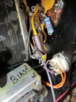
Hi Rod
Yes it is a supression type, all I had to hand. But it was good enough to have a look at the primary oscillation of interest.
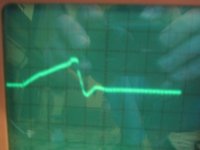
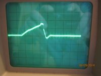
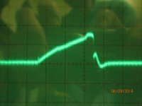
I soldered a 20k trimmer across the 10k, set initially to full value. The damping was inferior at 6k6. Went I went lower, oscillation became more and more extended. I then removed the 10k, and tried again. 10k does seem about as good as it gets. Going higher just introduces another peak, just before the overshoot. 15k was about the best compromise between keeping both peaks small. Attached are in order, left to right, of increasing R- 6k6, 10k, 15k, 20k
The supply was under it normal load, supplying 420 V @ 110 mA. I'm surprised that rectifier only seems to be conducting for 2 x 3mS per s! I thought choke input supplies conduct for a much longer part of the cycle, or am, as I suspect, missing something? 🙂
Paul
Yes it is a supression type, all I had to hand. But it was good enough to have a look at the primary oscillation of interest.
I soldered a 20k trimmer across the 10k, set initially to full value. The damping was inferior at 6k6. Went I went lower, oscillation became more and more extended. I then removed the 10k, and tried again. 10k does seem about as good as it gets. Going higher just introduces another peak, just before the overshoot. 15k was about the best compromise between keeping both peaks small. Attached are in order, left to right, of increasing R- 6k6, 10k, 15k, 20k
The supply was under it normal load, supplying 420 V @ 110 mA. I'm surprised that rectifier only seems to be conducting for 2 x 3mS per s! I thought choke input supplies conduct for a much longer part of the cycle, or am, as I suspect, missing something? 🙂
Paul
Attachments
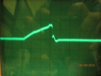
The choke supplies output current for a much longer period. Preferably without depleting it's energy store.
Time to optimise!
I'd prefer to use a transformer core, rather than a suppression ferrite, though - you may miss some HF nasties.
As for the choke-input filter, the conduction-angle depends on the L-value, the dc current, and the parasitic resistances. PSUD2 experimentation will show what to do, if longer conduction angles are desired.
Hi Rod
Re filament supply. I tried putting another 47R in parallel with fitted one- this had no effect at all. So presumably I need to go to higher values
I also had a look at my EZ80-rectified negative bias (300B) and driver supplies. As I feared I need more turns on my sniffer coil- any oscillation is masked by noise. I could just see some short lived ringing on the bias supply, using a x1 probe, and 1mV/div on my scope. Yes, I'll get some more suitable cores soon. Might just try e.g. 1n+10k for now
Thanks
Paul
Hi Rod
Gave up on the bias supply optimisation- I'll try again when I've made a more suitable sniffer coil.
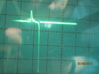
So I revisited the filament supply. With snubber C of 100n, varying R from a short to open circuit makes no difference at all to the basic profile. If you look closely at the figure in post 55, you can see a small positive peak just after the large negative one. Increasing R to 136R just eliminates this, as do all higher values. So I'll fit 150R to both phases
What is the large negative peak?
Paul
Gave up on the bias supply optimisation- I'll try again when I've made a more suitable sniffer coil.
So I revisited the filament supply. With snubber C of 100n, varying R from a short to open circuit makes no difference at all to the basic profile. If you look closely at the figure in post 55, you can see a small positive peak just after the large negative one. Increasing R to 136R just eliminates this, as do all higher values. So I'll fit 150R to both phases
What is the large negative peak?
Paul
Hi
Why is, what I presume to be the reverse conduction peak, so large? And why isn't the snubber affecting it?
Paul N
Why is, what I presume to be the reverse conduction peak, so large? And why isn't the snubber affecting it?
Paul N
Hi Paul,
The Full-Wave configuration accentuates the conduction & reverse current, as does the large forward current in the Ampere-level filament supply, and the 350-600pF+ of the 1N582x diodes. Maybe the leakage inductance of the transformer is very large.
It is also possible in this case that your measurement is being corrupted by B and E-field leakage around the transformer.
For accurate measurement, twisting the measurement cable, and shielding it all the way to the current-transformer coil may help. make the cable long enough to set the scope 2m or so from the transformer, and connect to a different ac-mains power socket, and of course use the transformer type (coupling-grade) toroidal ferrite.
- Status
- Not open for further replies.
- Home
- Amplifiers
- Tubes / Valves
- Standard Silicon Diode Rectifier's VS Ultra Fast