Okay I finally happened to try this swap out in a guitar amp/Plexi style circuit.....dumped the old standard silicon 1N4007s.... the
Ultra fast UF4007s were/are around same price so figured I give them a try...Just wow....I thought it was all hype/myth you wouldn't even notice the difference....
To me there is a Huge difference....first thing right off the bat was the response, its more touch sensitive/exact. I'm really impressed actually, just improved on a fuller/dynamic sound.
Last edited:
Yes, UF4007 emits much less noise at its switch-OFF.
A snubber circuit can remove much of the remaining noise (caused by leakage inductance of the transfomer): connect 47 ohm 1/2W resistor and 22nF 1500V (yes, really 1.5kV rated) across the trafo secondary.
Sometimes, the difference between rectifiers is accentuated by the electrolytic power supply capacitors. They age quickly in a hot amp, so if they are more than 8-10 years old, replace them with Nichicon or Panasonic parts, and you'll certainly notice the difference.
Being majority carrier only devices, Schottky diodes are "noiseless". Snubbing is not needed.
IMO, it makes great sense to use high PIV Schottky diodes in new designs and builds. There may be problems in retrofitting the TO220 cases into existing equipment. UFnnnn parts are drop in replacements for their 1Nnnnn counterparts.
IMO, it makes great sense to use high PIV Schottky diodes in new designs and builds. There may be problems in retrofitting the TO220 cases into existing equipment. UFnnnn parts are drop in replacements for their 1Nnnnn counterparts.
Yes, snubbing is still recommended, even though the conducted and radiated emissions from SiC rectifiers is lower overall, because of the lack of reverse recovery current pulses.
The major culprit is the leakage inductance of the transformer, which stores energy, and releases it at the moment the rectifier current passes through zero. The high capacitance of the diode hurts, too, as Wrenchone says. The snubber catches the pulse and turns it into heat in the resistor.
Don't hold back from trying the Cree SiC rectifiers, though. Keep their wiring (trafo-rectifier-cap) very short, use a snubber, and a modest-sized C1, to get best results.
Everything just feels far more snappy/quicker/precise response, Really liking that....upper frequencies are more interesting too, more smoother/transients etc....and just overall sustain/definition/Dynamic's has improved greatly...I can't get over how big of a change it really is...I figured there wasn't going to be much of a difference...true that high end "hash" has been reduced greatly....
Last edited:
If the transformer leakage inductance releases energy when the rectifier current passes through zero, would you expect any difference between a full wave rectifier with centre tap or a bridge rectifier without?
I have always tended to go with full wave as I dont like the idea of the bridge switching noise into the ground buss, but maybe I am miss thinking this")
I tend to use choke input for ht, but even here I have seen benefits from using snubbers, even with valve rectifiers.
I have always tended to go with full wave as I dont like the idea of the bridge switching noise into the ground buss, but maybe I am miss thinking this
I tend to use choke input for ht, but even here I have seen benefits from using snubbers, even with valve rectifiers.
Just because they're called 'fast rectifiers' doesn't mean they make the amp go any faster. They just produce less noise. Your amp has become less noisy. Nothing else has changed, other than your perception.Everything just feels far more snappy/quicker/precise response,
The energy stored in the leakage inductance causes trouble with any rectifier, unless it is routed into a resistor - the snubber.
The stored energy varies with the current flow at rectifier turn-OFF, so choke-input certainly helps.
I don't think that FW helps very much, though I have not tried them in an EMC chamber!
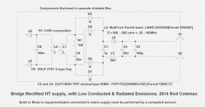
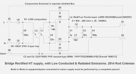
With bridge rectifiers, the best practice is to use very short wiring to the first cap. Then, only wire + and - of the first cap to the second cap - but with a series element in + and - lines. With choke-in filter you still have the little cap right after the rectifier, and cap-input is the same (but with larger cap).
Wire the second cap with the choke in the negative line, and in the positive line, either another choke, or a multi-turn bead:
28C0236-0BW-10 - LAIRD TECHNOLOGIES - FILTER, 6X10-15MM, 100MHZ, 835R | Farnell UK
This way, you should be able to keep the rectifier noise out of the second cap, right up to UHF (plenty of rectifier energy there, if you don't have a snubber).
O, perhaps I better add a drawing:
.
The stored energy varies with the current flow at rectifier turn-OFF, so choke-input certainly helps.
I don't think that FW helps very much, though I have not tried them in an EMC chamber!
With bridge rectifiers, the best practice is to use very short wiring to the first cap. Then, only wire + and - of the first cap to the second cap - but with a series element in + and - lines. With choke-in filter you still have the little cap right after the rectifier, and cap-input is the same (but with larger cap).
Wire the second cap with the choke in the negative line, and in the positive line, either another choke, or a multi-turn bead:
28C0236-0BW-10 - LAIRD TECHNOLOGIES - FILTER, 6X10-15MM, 100MHZ, 835R | Farnell UK
This way, you should be able to keep the rectifier noise out of the second cap, right up to UHF (plenty of rectifier energy there, if you don't have a snubber).
O, perhaps I better add a drawing:
.
Attachments
Hi Andrew,
L3 is the high-value choke that allows current to be drawn from the supply almost continuously (high conduction-angle filter). Otherwise known as choke-input filter.
The chokes must have sufficient energy storage:
1/2 L I^2
to maintain the near-continuous current, so L must be higher for low load currents.
In HT supplies, specially rated "choke-input" chokes are desirable, as they have extra insulation to prevent problems from the high end-to-end voltage:
Like these :
CHOKE INPUT FILTER CHOKES
CHOKE INPUT FILTER CHOKES
C1 is not large enough to hold the output voltage at a continuous level. Instead, it is dimensioned to slightly reduce the voltage swing across the choke, and at the same time, suppress (HF) noise coming in from the rectifiers.
Stacked construction in this part is also desirable, for low parasitic inductance.
Wima MKP4 will suffice:
MKP4O141007E00KSSD - WIMA - CAP, FILM, PP, 1UF, 1KV, RAD | Farnell UK
Stacked construction in this part is also desirable, for low parasitic inductance.
Wima MKP4 will suffice:
MKP4O141007E00KSSD - WIMA - CAP, FILM, PP, 1UF, 1KV, RAD | Farnell UK
neither does it achieve that in an rCLR, nor in an rCRC.C1 is not large enough to hold the output voltage at a continuous level.
The first smoothing cap stores some charge.
The transformer sees a capacitor input filter.
It does not see a "pure" choke input filter.
It seems to me that making the cap deliberately smaller just reduces the stored charge.
In an rCRC and in an rCLC one often sees the first cap smaller than the second cap.
No one then draws the conclusion that the first cap does not exist.
In this case the ratio is extreme 1:100
So what I am asking is:
what effect does the first cap have on the way the choke operates?
Or what does L3 do in the presence of C1?
- Status
- This old topic is closed. If you want to reopen this topic, contact a moderator using the "Report Post" button.
- Home
- Amplifiers
- Tubes / Valves
- Standard Silicon Diode Rectifier's VS Ultra Fast