Hi Rod
I've ordered some more suitable ferrites, and will implement the measures you recommend. But, assuming reverse conduction is high, how do I alleviate it? Might a different schottky type help?
Paul
From memory, the oscillatory frequency was about 10kHz. I'll recheck, as this suggests a leakage inductance which is ridiculously high at 360mH! (Taking 2n2 as the dominant capacitance, as the GZ37 will add only a few pF.)
Thanks
Paul
....................Suppression grade ferrites (data sheets show losses versus frequency) may cause a loss of high frequency information. I suspect the sleeve you have there is a suppressor.
Nice toroidal core, costs only pennies:
B64290P37X830 - EPCOS - FERRITE CORE, TOROID, N30 | Farnell UK
ideal for snubber caibration.
I'd prefer to use a transformer core, rather than a suppression ferrite, though - you may miss some HF nasties....................
What are the key clauses in a toroid specification that tell us transformer grade or suppression grade?..................... and of course use the transformer type (coupling-grade) toroidal ferrite.
How do we tell them apart?
I have a few Epcos N30 and T38 toroids in stock, just a fraction bigger than B64290P37X830 and wonder whether they are suppressors, or transformers !
I also have a tiny toroid saved from a dead USB charger, but don't have any data.
I do suspect some measurement error. But transformers with excessive leakage inductance do exist, and you could measure it (which is fun).
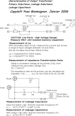
Use a resonance search with a handy cap value (10-68n), and do as our Forum colleague Yves would do: (thank you Yves, for the copyleft!):
You can blame me for any errors in the translation.
Use a resonance search with a handy cap value (10-68n), and do as our Forum colleague Yves would do: (thank you Yves, for the copyleft!):
You can blame me for any errors in the translation.
Attachments
Hi Rod
Thanks. BTW don't know why I mentioned a 2n2 and GZ37- this the filament supply! 😱 . 10kHz and 100n suggests a leakage inductance of 2.5mH- still high. The transformer core ferrites are on their way, I'll recheck f then
Paul
Thanks. BTW don't know why I mentioned a 2n2 and GZ37- this the filament supply! 😱 . 10kHz and 100n suggests a leakage inductance of 2.5mH- still high. The transformer core ferrites are on their way, I'll recheck f then
Paul
Why the 50mAac current limit for the test of Lp?
In tests 3 & 4 for Lf and Cp,
what do we look for on the scope to confirm peak of the resonant frequency?
Minimum height of signal, or maximum height of the signal?
In tests 3 & 4 for Lf and Cp,
what do we look for on the scope to confirm peak of the resonant frequency?
Minimum height of signal, or maximum height of the signal?
What are the key clauses in a toroid specification that tell us transformer grade or suppression grade?
How do we tell them apart?
I have a few Epcos N30 and T38 toroids in stock, just a fraction bigger than B64290P37X830 and wonder whether they are suppressors, or transformers !
I also have a tiny toroid saved from a dead USB charger, but don't have any data.
How to tell:
1. transformer cores have an AL value, and usually state that the Application is in broadband transformers.
2. Suppression cores have losses quoted in the data. Look for Ohms at 100MHz, for instance.
Toroids in consumer equipment are sure to be suppressors, unless it it obviously in a transformer position. Don't use unless you are sure.
The N30 cores are very suitable, it's a transformer grade for sure, and should give low enough losses in this application up to 10MHz.
Material Data:
http://www.epcos.com/blob/528848/download/3/pdf-n30.pdf
Note that line 1 of this data gives the design Application.
Rectifiers can generate reverse-recovery spectrum at frequencies above 10MHz. If you want to see these components, and you have a scope with bandwidth to do so, simply holding the probe in the neighbourhood of the rectifier will give the wave-shape at least.
Why the 50mAac current limit for the test of Lp?
In tests 3 & 4 for Lf and Cp,
what do we look for on the scope to confirm peak of the resonant frequency?
Minimum height of signal, or maximum height of the signal?
It's connected as an L-C parallel tank. So at resonance, the impedance is very high, and the 47K series resistor drops little voltage.
Therefore, seek the largest amplitude.
Hi Andrew
The cores Rod recommended are available on Ebay-
EPCOS,B64290P37X830,FERRITE RING CORE, 6.3X3.8X2.5 | eBay
Much higher unit price that Farnell,but you buy one for 1.65 delivered and avoid Farnell’s minimum order value and carriage charge. Don’t know if it’s universally true, but note this core is silvery in colour, not black as all the suppression cores I’ve seen are
Paul
I already have a few. Just a little bit bigger. I got all 6 toroids for less than that £1.64 charge.Hi Andrew
The cores Rod recommended are available on Ebay-
EPCOS,B64290P37X830,FERRITE RING CORE, 6.3X3.8X2.5 | eBay
Much higher unit price that Farnell,but you buy one for 1.65 delivered and avoid Farnell’s minimum order value and carriage charge. Don’t know if it’s universally true, but note this core is silvery in colour, not black as all the suppression cores I’ve seen are
Paul
When I start researching a new project I generally find I have >90% of components in stock.
I accumulate an order which could be 6months away and order the missing components for maybe 6 projects that are being researched.
Generally I order by the dozen, or by the hundred, not ones and twos. That way I minimise postage costs and waiting time.
I don't have any project waiting for bits and wasting time. Researching uses up all my time.
Actually I do have one project. The LNA testing kit which has many specialised ICs, that I don't carry.
Last edited:
It's a very helpful thread! I am so glad I came across. Can you please help me understand how should it look like with multiple transformers? Do I need to have L5, L6, and C5 for each transformer? Also, are L5, L6 the same to L4? Thank you!
It's a very helpful thread! I am so glad I came across. Can you please help me understand how should it look like with multiple transformers? Do I need to have L5, L6, and C5 for each transformer? Also, are L5, L6 the same to L4? Thank you!
Yes, apply the trafo-primary's filter components L5, L6 & C5 to every transformer, if possible. The ferrite beads MUST be insulated with sleeving (eg Heatshrink).
L5, L6 and L4 are there to soak up any high frequencies that might be generated in the rectifiers or come up through the mains supply. The exact type is not important, but the modern multiple-turn beads are remarkably effective at suppressing noise from HF to UHF. I have been using the Wuerth Elektronik WE-UKW series in the EMC test lab recently, and these are my current favourites.
WE-UKW EMI Suppression 6-Hole Ferrite Bead - Product Catalog Passive Components
Any of these will be useful, though the 6-hole types are best.
Please remember to fully insulate them and fix them in place.
Tried adding R1, C4, and C1 and got unexpected results. I used a current transformer (B64290P37X830 EPCOS (TDK) | 495-3874-ND | DigiKey) to get oscillograms below. The first image is without any R,C,L between PT, rectifier and choke. The second image is an impulse from the first image in all its glory. The third image is with R1 (100Ohm) and C4 (50n). The fourth image is with the R1, C4, and C1 (1uF), and L4. Is it possible that C1 and choke L3 resonate?
I used stealth Fairchild diodes, C1 BFC233810105 Vishay BC Components | BC1576-ND | DigiKey, tried various caps for C4.


I used stealth Fairchild diodes, C1 BFC233810105 Vishay BC Components | BC1576-ND | DigiKey, tried various caps for C4.
It looks like the C4 value should be somewhat larger than 50n, but with a larger resistor value, maybe into the Kohm range. But first, tell us more about the configuration -
-exact diode type,
-PT ratings,
- dc load current;
-nr. turns on the current transformer.
.
-exact diode type,
-PT ratings,
- dc load current;
-nr. turns on the current transformer.
.
Rod, thank you so much for helping me!
Diodes are ISL9R8120P2. PT is custom made Heyboer with 440VCT @0.1A and 440V @0.2A secondaries and +/-10% adjustment on primary. At the moment its running 2x6E5P @ 13mA each plus 13mA resistive shunt on 440V secondary (40mA total) and about 17mA total on 440VCT (10mA OA2 tube load and 7mA shunt). The transformer does get a little bit worm after 2-3hrs.
I put 12 turns of 40AWG on the current transformer.
I tried 0.1uF and 22nF for C4 with 100Ohm and 200Ohm with the same result. I will try larger values and I will post results later today.
I see two types of impulses on the scope:
- one is very short with about 200mV amplitude on image 1 (also image 2). this one gets stronger to 400mV with introducing C4, R1.
- another one is with much smaller amplitude. This one gets really bad with introducing C1 (last image).
PS: some or all of the results may be just user error.
Last edited:
Yes, the first pulse in image-4 is expected - adding C1 (1uF after rectifier) will cause some turn-ON forward current to flow (the traces are measuring current, rather than voltage).
The optimised snubber can be tuned until the ringing after this first pulse is damped out as best as possible. I would certainly expect to improve on image-4.
I suspect that the Fairchild Stealth diode may be a little over-large. The capacitance increases in bigger diodes, and tuning the snubber may well be easier with UF4007 diodes (very cheap). These are my usual choice for B+ rectifiers, and the Trr of 75ns is OK.
I have an LC filter with 30H and 4,700uF. I calculated the max current to be around 170mA for 400V. Is it correct? Just want to make sure that the current will not exceed 1A for UF4007.
I will get UF4007 and report back.
I will get UF4007 and report back.
Received UF4007. Pretty much same result. The first image is with ISL9R8120P2 the second is with UF4007. Both with no RC added. My filter is LCRC.


I tried with various caps from 10nF to 0.1uF and various resistors from 100Ohm to 2kOhm. The first image is no RC, the second is 100Ohm 68nF and the third 100Ohm 22nF. C1=1uF. The first image looks cleaner and not much difference between 22n and 68n.


Is it expected? What can I try?
I tried with various caps from 10nF to 0.1uF and various resistors from 100Ohm to 2kOhm. The first image is no RC, the second is 100Ohm 68nF and the third 100Ohm 22nF. C1=1uF. The first image looks cleaner and not much difference between 22n and 68n.
Is it expected? What can I try?
Last edited:
- Status
- Not open for further replies.
- Home
- Amplifiers
- Tubes / Valves
- Standard Silicon Diode Rectifier's VS Ultra Fast