I see coaxial cable continues to be marketed by Van den Hul as it was over 30 years ago. I have a small length of this my cable collection, this having a brown jacket. It would have been nice if it had been less rigid and had plugs to suit but I deemed it unusable in our living space. This cable is expensive and would have to be sourced from other than electronics suppliers in Australia. I did not pursue this - there is a lot of capacitance in your transmission line it is understandable this gives rise to high levels resonance. I have not done a Tian plot but your cable may require unity gain stability.Coaxial cable simulation
View attachment 1240105 View attachment 1240106 View attachment 1240107
Alternative sim circuit
View attachment 1240108 View attachment 1240109
Class AB amp (without output coil) oscillations with long unloaded coax cable
View attachment 1240110 measured impedance View attachment 1240111
Last edited:
I do. It is called a speaker.You MUST use output coil in this design.
I read Rod Elliot's notes on P3A, it says at least a minimum +/- 30VDC supply voltage is required for a stable operation.
My query is - do any component values needs to be changed to make it work on voltages +/- 20VDC or even little bellow like +/- 15VDC? As I don't need very high output and to avoid high heat dissipation
My query is - do any component values needs to be changed to make it work on voltages +/- 20VDC or even little bellow like +/- 15VDC? As I don't need very high output and to avoid high heat dissipation
Last edited:
+/-15VDC is too low to get any good performance from it, but it'll work on the bench. You better use chipamps at that voltage level. TDA2030A is a good choice. Working on a subwoofer project where I'm going to use TDA2050L.
Last edited:
Jesus. Just build the darn thing with rods parts list, if it plays great,perfect, want more , change some parts , listen again,
Thats what I did., no problems at all, did my "improvement" help? I doubt it..
Thats what I did., no problems at all, did my "improvement" help? I doubt it..
Class AB amps like Rod's P3A only generate lots of heat when you hit them hard. Unlike Class A.As I don't need very high output and to avoid high heat dissipation
The reason for this is due to the property of a transistor in a common emitter stage i.e.Q4. The internal collector to base capacitance has an inverse relationship with the square root of the voltage applied to Q4 collector and this internal capacitance will increase out of normal proportions. As you have read from Rod Elliott's notes the result will be instability. If you build your amplifier according to these notes and run it at low output levels the level of heat generated will be at the low end of the scale.I read Rod Elliot's notes on P3A, it says at least a minimum +/- 30VDC supply voltage is required for a stable operation.
My query is - do any component values needs to be changed to make it work on voltages +/- 20VDC or even little bellow like +/- 15VDC? As I don't need very high output and to avoid high heat dissipation
Thanks for your detailed explanation.The internal collector to base capacitance has an inverse relationship with the square root of the voltage applied to Q4 collector and this internal capacitance will increase out of normal proportions.
Na I just buy what ever is being sold in my countries market.
I have just purchased every PCB made in my country and built up a collection of AMPs.
if you don't mind.
can you post pics of those PCBs, I like to see your collection of P3A PCBs
Speaker is placed behind the speaker cable. The possible instability I tried to explain has an origin in input capacitive impedance (at discrete high frequencies above 1MHz) of the cable as a transmission line, cable open at the end, which is the equivalent of speaker inductive load. I have shown simulations, I have shown measurements and real life example of oscillations. I cannot do anything more.I do. It is called a speaker.
G'day Guys,
I have finished putting the P3A into the new chassis.
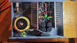
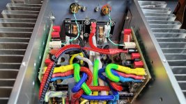
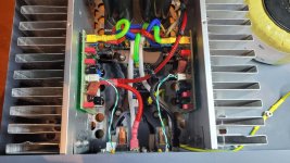
During the process I removed the 100nF cap across the bias spreader Q9 as testing had shown this gave no improvement.
My square waves now look a bit better on a 4R load. The overshoot is now gone.
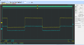
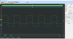
The sine wave still seems to have the same old 'grass' on a 4R load.

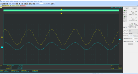
The 10k sine wave looks a bit odd but I think the blame on that goes on the sig gen.
A quick count of the peaks gives 13 peaks within a 200us division.
200/13 = 15.38
1/0.00001538 = 65019 Hz.
Which is exactly what somebody suggested earlier in the thread.
So I still have a bit of oscillation to deal with.
I will ponder the next step overnight however right now I am tempted to try the suggestion of Tombo and slide some ferrite beads over the legs of the emitter pins on the driver transistors Q5/Q6.
I have finished putting the P3A into the new chassis.


During the process I removed the 100nF cap across the bias spreader Q9 as testing had shown this gave no improvement.
My square waves now look a bit better on a 4R load. The overshoot is now gone.


The sine wave still seems to have the same old 'grass' on a 4R load.


The 10k sine wave looks a bit odd but I think the blame on that goes on the sig gen.
A quick count of the peaks gives 13 peaks within a 200us division.
200/13 = 15.38
1/0.00001538 = 65019 Hz.
Which is exactly what somebody suggested earlier in the thread.
So I still have a bit of oscillation to deal with.
I will ponder the next step overnight however right now I am tempted to try the suggestion of Tombo and slide some ferrite beads over the legs of the emitter pins on the driver transistors Q5/Q6.
Your dc protection circuit is close to your inputs where output radiated fields will be present. Your input wiring ought to be upgraded to something with better shielding. You will have to dismantle some of your work to put a ferrite bead on the emitter leads of Q5/Q6. In practice your signal control point has to be in series with Q1 base lead which is where a ferrite bead should be deployed. You can put that at the end of the new signal wire at the point where this connects to the input terminals. Microphone cable has better shielding properties as there is a braid covering 4 available wires- you can use this for external cables.G'day Guys,
I have finished putting the P3A into the new chassis.
View attachment 1243134
View attachment 1243135
View attachment 1243136
During the process I removed the 100nF cap across the bias spreader Q9 as testing had shown this gave no improvement.
My square waves now look a bit better on a 4R load. The overshoot is now gone.
View attachment 1243137
View attachment 1243138
The sine wave still seems to have the same old 'grass' on a 4R load.
View attachment 1243139
View attachment 1243140
The 10k sine wave looks a bit odd but I think the blame on that goes on the sig gen.
A quick count of the peaks gives 13 peaks within a 200us division.
200/13 = 15.38
1/0.00001538 = 65019 Hz.
Which is exactly what somebody suggested earlier in the thread.
So I still have a bit of oscillation to deal with.
I will ponder the next step overnight however right now I am tempted to try the suggestion of Tombo and slide some ferrite beads over the legs of the emitter pins on the driver transistors Q5/Q6.
Douglas Self discussed this in chapter 27 (Power Amplifier Input Systems) of his Amp Design book. He has the input filter at 10R and 1n for a 3dB frequency of 15.9MHz.
that filter does nothing, its way too high.
in that book you reference, does it state that the hpf does anything else other than the obvious ?
His argument is that the source impedance will not be zero. He suggests for an active source, it's 30R at best and likely more like 100R. So, the RC network has an effective R of 40 to 110 putting the corner somewhere in the 1.4 to 4 MHz range.
If you agree that a typical active source is around 100R, then this seems reasonable to me.
His designs place great emphasis on low noise. The input R is one of the leading contributors to noise, so if you can keep this down, it fulfills his objectives. He goes on to state that the highest value he uses is 47R to keep noise low. At 147R (47 + a 100 source) the 3db frequency gets much closer to 1MHz
I'm simply stating his arguments. I don't think there's a single right answer here. It depends on your priorities and if you know what your source impendence will be.
Last edited:
yesYour dc protection circuit is close to your inputs where output radiated fields will be present. Your input wiring ought to be upgraded to something with better shielding. You will have to dismantle some of your work to put a ferrite bead on the emitter leads of Q5/Q6. In practice your signal control point has to be in series with Q1 base lead which is where a ferrite bead should be deployed. You can put that at the end of the new signal wire at the point where this connects to the input terminals. Microphone cable has better shielding properties as there is a braid covering 4 available wires- you can use this for external cables.
use for example RG 316 - cheap and big enough to solder.
Your input signal has an additional parasitic high frequency component present. To me it looks like this is being amplified along with the desired signal. At least you are making some progress. If you short the input to ground what do you see on the output when no load is connected (CRO trace picture)? What driver and output devices are you now using?The sine wave still seems to have the same old 'grass' on a 4R load.
- Home
- Amplifiers
- Solid State
- Stability testing my new Rod Elliot P3A