Hi,
0.3mm diameter is only 0.07sqmm, that is tiny for output currents.
0.45mm is only a little larger than tiny.
0.6mm is 0.28sqmm and even that is pretty small. I would use double 0.6mm for power lines and outputs. AND keep them short.
Are the 0.3 or 0.45 enamelled?
Then grouping them into bundles of 8 to 12cores may sound quite nice if the claims made for insulated multicore are to be believed.
UEW thickness problem.
Thank you AndrewT.
By surfing the net, I found the following (refer to http://elm-chan.org/docs/wire/wiring_e.html).
0.16 or 0.2mm dia UEW is equivalent to 0.5 or 0.9 mm width printed pattern.
Considerring the pattern thickness of general pcb(0.035mm), I think this is almost correct.
So, 0.3 or 0.45mm dia UEW is equivalent to about 2.0 or 4.5mm width printed pattern.
If my calculations are correct, the UEWs I used are not thin compared to the pcb by sixtek.
Anyway, I'll keep on testing and monitoring what happens to my ST151.
Thank you so much.
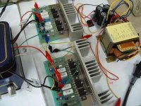
Testing...
Testing with just normal volume level.
So good until now.
Amp not connected, the voltage is (+,-) 32.10V
When the amp is connected and turned on,
the voltage is dropped to (+,-) 31.42V.
Does this means that the transformer should be larger
or just ok?
Testing with just normal volume level.
So good until now.
Amp not connected, the voltage is (+,-) 32.10V
When the amp is connected and turned on,
the voltage is dropped to (+,-) 31.42V.
Does this means that the transformer should be larger
or just ok?
Attachments
Hi,
just 700mV drop when quiescent load connected seems about right or just lower than normal.
What quiescent current is the amp drawing?
Have you tried measuring the hum on the supply lines when the amp is just idling (input shorted).
just 700mV drop when quiescent load connected seems about right or just lower than normal.
What quiescent current is the amp drawing?
Have you tried measuring the hum on the supply lines when the amp is just idling (input shorted).
No serious hum.
Thanks, AndrewT.
I don't know about the quiescent current.
Could you tell me how to measure or calculate it?
I just tried to listen to the hum with source just stopped
at min. volume and max. volume.
There is only a very little hum at max. volume.
Everything is just fine until now.
Sound is also very good than I expected to be.
Re: No serious hum.
Measure the voltage drop over one of the 0.33R resistors. Then ohms law, I = V/R
Multiply that by 2 as there are two sets of output transistors.
This current is adjusted by the preset P1. There's not really any hard and fast rules on setting this, many people have different opinions 🙂 I'd set it for 40mA per pair, so adjust until you read about 13mV over one of the resistors.
You will need to adjust the bias, then let the amplifier warm up, and readjust it to match
cantabile said:I don't know about the quiescent current.
Could you tell me how to measure or calculate it?
Measure the voltage drop over one of the 0.33R resistors. Then ohms law, I = V/R
Multiply that by 2 as there are two sets of output transistors.
This current is adjusted by the preset P1. There's not really any hard and fast rules on setting this, many people have different opinions 🙂 I'd set it for 40mA per pair, so adjust until you read about 13mV over one of the resistors.
You will need to adjust the bias, then let the amplifier warm up, and readjust it to match
The quiescent current.
Thanks, jaycee.
As sixtek said, I set P1 so that the voltage drop
over one of the 0.33R resistors is about 10mV.
After the amplifier warmed up, it reads 10.9mV.
Somewhat higher but I didn't adjust again.
I calculated and got 33mA for that registor.
Then, 66mA will be the quiescent current as you said.
Nice built, Cantabile!!! universal pcb very professional!!
"2. As you see in the pictures, I used general and cheap parts.
OK with the parts? Or are there some unsuitable parts?"
- in brazil is not so general parts!! hehe!
I´m glad to know that 1943/5200 transistors works fine on this amp. I will test.
And, one more time, Thanks Sixtec!!!
"2. As you see in the pictures, I used general and cheap parts.
OK with the parts? Or are there some unsuitable parts?"
- in brazil is not so general parts!! hehe!
I´m glad to know that 1943/5200 transistors works fine on this amp. I will test.
And, one more time, Thanks Sixtec!!!
Hello, question from the newb here!
I have a set of 2sa1301/2sc3280 here. Can i use them with this amp? Which driver set should i use? Power supply voltage?
Thanks
I have a set of 2sa1301/2sc3280 here. Can i use them with this amp? Which driver set should i use? Power supply voltage?
Thanks
Hi to every one
I finished the ST151, I use a +-40v supply and when I make some measurements I find -40v on the output without load, the fuse didn’t burn. I double check everything and seem to be ok.
The output transistors and the driver didn’t burn. I used the transistors of the original schematic.
I connected a 100hom resist on the +40v and other 100hom on the -40v and when I turn on the amp have a 0,9v drop on the -40v line resist.
I didn’t connect any load to the output. What can be the problem?
Need help
Hi Augusto
SOmetimes transistors short without appearing to blow. (Usually the plastic case can be damaged though).
To get -40V rail voltage maybe the BD140 driver has gone short, or perhaps there is a shorted track between the base and collector of this or the BD139 current source.
ALternatively, maybe the VAS BD140 has got an open circuit somewhere.
Suggest you check the tracks and see if any CB shorts (connecting the meter leads on resistance with reverse bias on CB should show a problem: most analogue meters have + out on the - lead but some digital meters have + out on + lead when measuring resistances) or CE shorts in the case of the BD139 CS and BD140 driver.
cheers
John
Thanks, i'll try this to see if solve the problem wen i go home
Or maby a fake transistor on may amp.
I will disconnect the bases of the Bd250 the Bd249 to see what happen on the output
Can a fake bc547 on the protection circuit cause the problem?
Or a big hammer will solve all the problems eh eh eh, just joking
Or maby a fake transistor on may amp.
I will disconnect the bases of the Bd250 the Bd249 to see what happen on the output
Can a fake bc547 on the protection circuit cause the problem?
Or a big hammer will solve all the problems eh eh eh, just joking
If you didn't connect any load I think you might not have blown anything. More likely a shorted track or open/bad solder joint.
st151 ,is'nt that a Toyota!?(carina I think).. hmm schematic seems ok hmm I'm sure it would sound ok, I did almost the exact same thing but with fet's
I remember I purchased a kit 200watt from some website
I will try to find the pics i took while testing it
and i will post it later..
It sounded great and it was pretty powerful
run on +- 45 volts DC
(sorry its something out of the current discussion)
I will try to find the pics i took while testing it
and i will post it later..
It sounded great and it was pretty powerful
run on +- 45 volts DC
(sorry its something out of the current discussion)
Need details of st151(150 watts)
Hi all,this goes to macd...i want to make st151 so that t can produce a power of around 150 watts on 4 ohms and it should be stable...i have a transformer of +\- 38 volts...can you post all the relevant documentation and schematics so that i can begin that project...m a newbe and dont know that much about electronics but this seems a goog amp...i choose you coz i saw your voltages to be high and thugt if urs is stable,then thats the one....thank yoy in advance.my email address is michaelmugambi@yahoo.com.
Hi all,this goes to macd...i want to make st151 so that t can produce a power of around 150 watts on 4 ohms and it should be stable...i have a transformer of +\- 38 volts...can you post all the relevant documentation and schematics so that i can begin that project...m a newbe and dont know that much about electronics but this seems a goog amp...i choose you coz i saw your voltages to be high and thugt if urs is stable,then thats the one....thank yoy in advance.my email address is michaelmugambi@yahoo.com.
- Status
- Not open for further replies.
- Home
- Amplifiers
- Solid State
- "ST151" 100W amplifier