I would probably use more powerful transistors for drivers than MJE340/350.
Also beware - are you sure those 2SA1943/2SC5200 will be genuine ? There are a lot of fakes...
Also beware - are you sure those 2SA1943/2SC5200 will be genuine ? There are a lot of fakes...
Hi, I was just about to start stuffing a Home made board useing your Design but was wondering a few things....
I don"t have any BC547/557 so Can I use BC550C/560C without much problems??
I also don"t have any BD249/250 so I was going to use some MJE3055/2955 T0-220..... Do you see any Problems with this or have any Advice??
Also would it be possible to use darlingtons at the output as I have a small supply of MJ11015/11016 T0-3 Darlingtons......
Thanx a Lot......
Hi,
Yes BC550C/560C is just perfect.
MJE3055/2955's SOA is not enough. If you'll use the amplifier with only 8 Ohm speaker then they'll be OK.
About darlingtons I'd say no...
Cheers,
http://sixtek.uw.hu/st151.html
Yes BC550C/560C is just perfect.
MJE3055/2955's SOA is not enough. If you'll use the amplifier with only 8 Ohm speaker then they'll be OK.
About darlingtons I'd say no...
Cheers,
http://sixtek.uw.hu/st151.html
ST151 Problem
Hi Sixtek
I finished my amp last night. Use +-30V from my lab power supply and switched on the amp. Every thing ok. I ajust the bias and when I connect a load (4R test load) the amp -40V supply shorts. (current limit). The +40V supply is ok. I double checked my components and checked my placements. Everything looks ok. I used the transistors from my previous post. What can be the problem?????? I will do some more checks and double check my circuit again. Can you supply me with some test voltages???
Thanks
macd
Another ST151
Hi Sixtek
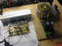
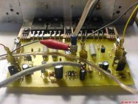
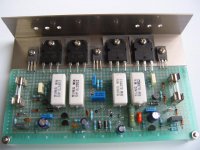
I found my problem with my amp. The amp is working fine. Sounds great and very stable. The bias current is set to 10mA(9.8mA). My supply is +-49V DC. The outputs are 2SC5200/2SA1943. Working okey. Tested it for about 1hr driving 8ohm load and still okey. Busy with my second channel. See photo's below of completed channel. Thanks for this amp and design. Will keep you posted.
Thanks
macd🙂 🙂 🙂 🙂
Hi Sixtek
I found my problem with my amp. The amp is working fine. Sounds great and very stable. The bias current is set to 10mA(9.8mA). My supply is +-49V DC. The outputs are 2SC5200/2SA1943. Working okey. Tested it for about 1hr driving 8ohm load and still okey. Busy with my second channel. See photo's below of completed channel. Thanks for this amp and design. Will keep you posted.
Thanks
macd🙂 🙂 🙂 🙂
Attachments
Another ST151
Hi sixtek
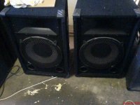
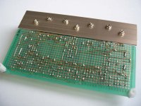
My bias current is 30mA and not 10mA. I have a 10mV drop across the 0.33ohm resistor. Sorry my mistake. Here is a foto of my speakers that I used to test this amp. When I connect them in parallel(4ohm load) the amp is still stable with a fan cooling the heatsink. Great amp. Thanks.
macd😉 😉 😉
Hi sixtek
My bias current is 30mA and not 10mA. I have a 10mV drop across the 0.33ohm resistor. Sorry my mistake. Here is a foto of my speakers that I used to test this amp. When I connect them in parallel(4ohm load) the amp is still stable with a fan cooling the heatsink. Great amp. Thanks.
macd😉 😉 😉
Attachments
Hi,
some of our amplifier experts here suggest (strongly) that Vre should be between 15mV and 25mV.
D.Self also goes for near 25mV for an Emitter Follower (EF) stage.
If you can keep your amplifier cool enough it might be worth trying this higher range of bias to keep out of the ClassB distortion region.
Pity your PCB prevents you mounting the output devices direct to the heatsink.
Since you use the aluminium angle for indirect mounting, I suggest you use at least 5mm thick aluminium angle and preferably nearer 8mm when the leg length is that long.
Bias current for ST151
Hello AndrewT
Thank you for this advice. I will ajust the current to +-20mV across the emitter resistors. My bias current will then be +- 60mA.
Will monitor the temperature after ajustment. Thanks😉 😉
Macd🙂 🙂
Hello AndrewT
Thank you for this advice. I will ajust the current to +-20mV across the emitter resistors. My bias current will then be +- 60mA.
Will monitor the temperature after ajustment. Thanks😉 😉
Macd🙂 🙂
Hi,
60mA per device=120mA total bias.
Pq will be 0.12*(+Vdc-(-Vdc))watts.
Don't run that many watts through that thin angle.
60mA per device=120mA total bias.
Pq will be 0.12*(+Vdc-(-Vdc))watts.
Don't run that many watts through that thin angle.
Bias Ajustment of ST151
Hi AndrewT,
Can you please explain what do you mean when you say "60mA per device" ??? Does this mean that after the bias ajustment the total current from the supply during idle state is 120mA. Is this 120mA from the + supply rail and120mA from the -supply rail??? Do I need to measure across all the emitter resistors and get a voltage reading of 20mV, thus 60mA thru each device and a total of 120mA from the + rail and 120mA from the -rail. Is this right?
The heatsink I am using is my test heatsink. The one I am planning to use is much bigger. I will change my angle shape iron to a much thicker one(+-8mm). Is this ok? I am planning you use a fan in my final build to cool the heatsink.
Thanks
macd🙂 🙂 🙂
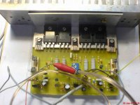
2 channels built. Testing...
Hi,
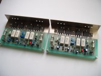
I built 2 channels on the universal pcb and testing with +,-31V.
I used pots at the input(100k A type).
TIP35C, TIP36C, BD139, BD140, BC547, BC557 are used.
No serious problems by now but I have some questions.
1. The sound is somewhat small. Is this by the low voltage?
Then, I will get a transformer and test again later on.
2. As you see in the pictures, I used general and cheap parts.
OK with the parts? Or are there some unsuitable parts?
Thanks again everyone and especially, Sixtek.
Hi,
I built 2 channels on the universal pcb and testing with +,-31V.
I used pots at the input(100k A type).
TIP35C, TIP36C, BD139, BD140, BC547, BC557 are used.
No serious problems by now but I have some questions.
1. The sound is somewhat small. Is this by the low voltage?
Then, I will get a transformer and test again later on.
2. As you see in the pictures, I used general and cheap parts.
OK with the parts? Or are there some unsuitable parts?
Thanks again everyone and especially, Sixtek.
Attachments
Re: 2 channels built. Testing...
In my questions above,
1. The sound is somewhat small.
-> Solved. Sorry. It was because of my mistake.
The output sound level of the source device(PC) was low.
I have another question.
The pop noise is somewhat large when power is on.
Is there any simple solution?
In my questions above,
1. The sound is somewhat small.
-> Solved. Sorry. It was because of my mistake.
The output sound level of the source device(PC) was low.
I have another question.
The pop noise is somewhat large when power is on.
Is there any simple solution?
Simplest solution - connect speakers through a relay that has a time delay on switch on. You can also add to that a DC-Protect circuit should the amplifier ever fail.
Only one comment on your PCB's - the wiring used for the output transistors looks a little thin.. better to use some thicker wire for this, or 2-3 pieces of your point to point wire twisted together.
Only one comment on your PCB's - the wiring used for the output transistors looks a little thin.. better to use some thicker wire for this, or 2-3 pieces of your point to point wire twisted together.
Thank you jaycee.
Thanks a lot jaycee.
Let me consider and try relay and DC-filter later on.
I used 2 kinds of wire thickness.
According to the sixtek's diagram( http://sixtek.uw.hu/st151_beult.pdf ),
0.45mm UEW for the power lines and the output transistors.
And 0.30mm UEW for all the other connections.
They say that 0.30mm UEW is actually more effective
than the leads of the normal resistors and capacitors.
Anyway, is your recommendation
"2-3 pieces of your point to point wire twisted together"
means that I'd better twist 2 or 3 of my UEW lines together and
use that for more thickness?
- Status
- Not open for further replies.
- Home
- Amplifiers
- Solid State
- "ST151" 100W amplifier