sparkle said:nice - what is the use of Q10 and Q14
thx
q10 and q14 are parts of protection circuit
i though it might be but was not sure....thanks - nicely done....
it woul be nice to hear how it will sound 🙂 when it is done....
it woul be nice to hear how it will sound 🙂 when it is done....
i have seen the pictures and the revised pcb.....but didn't hear the comments about the sound because the amp is not working yet....that is why i said "when it is done"......(it is not working yet - right ?! maybe i missed something) ..
i really like the protection circuit... 🙂
i really like the protection circuit... 🙂
Your amplifier schematic is just a traditional one from decades, what is the new thing in it to attract someone,same old topologies again and again.
Have you read my first post, man?!
Anyway thanks for your "kind" comment...
ST151 is not a state-of-art design, uses nothing new or special circuit.
Anyway thanks for your "kind" comment...
sixtek said:Have you read my first post, man?!
Anyway thanks for your "kind" comment...
Do you love repeating history. 🙂
some "veteran" things sound extremely good even today....so i don't see the point...
look for example Audio Note - it uses nothing new - and some of the tubes are produces in the years i was not even born....some of them even earlier when my father was not born...
i really do not see the point of the veteran expression....
the point is in sounding good - does not matter how old the design is.....
look at the John Linsley Hood amplifier that was first made in 1969 or look the year when differential input stage was discovered and it is still used in almost 90% of the todays amplifier 😕
A good implementation of a tried and tested topology is a good thing 🙂
We all have to begin somewhere. Power amps based around expensive outputs etc are daunting for the newcomer, as mistakes can be super costly. This is a nice little design that you could use with anything from the mentioned BD249/250 or TIP35C/36C, to the 2955/3055, 15003/4 or even MJL21193/4.
We all have to begin somewhere. Power amps based around expensive outputs etc are daunting for the newcomer, as mistakes can be super costly. This is a nice little design that you could use with anything from the mentioned BD249/250 or TIP35C/36C, to the 2955/3055, 15003/4 or even MJL21193/4.
Amp Done!!
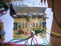
I finished to build amplifier ST151. My problem is in relation the regulation of the bias setup. I know that trimpot 1K regulates the bias on the amplifier. How to make the measurement and adjusting to the value?
The amplifier works fine, but the transistor gettind hot in short time(1~2 min.). The speaker is a behringer monitor1c, impedance is 4 ohms, perhaps because this, but i really think that if i let the amp at full power more than 5 min, the transistors will dead.
See the picture of my amplifier!
P.s: in Brazil, good capacitors is expensive$$
Hi,
Thanks for posting the image. Nice built!
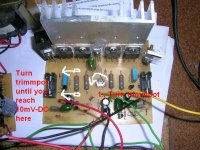
Bias adjustment:
1., before turning on the amplifier adjust the 1k trimmpot to maximum
2., then turn on the amp, and let's measure the voltage on one of the 0.33 Ohm resistors. slowly turn the 1k bias trimmer to reach 10mV on the 0.33 Ohm resistor.
Good luck!
Thanks for posting the image. Nice built!
Bias adjustment:
1., before turning on the amplifier adjust the 1k trimmpot to maximum
2., then turn on the amp, and let's measure the voltage on one of the 0.33 Ohm resistors. slowly turn the 1k bias trimmer to reach 10mV on the 0.33 Ohm resistor.
Good luck!
New files, with better PCB design:
Schematic:
http://sixtek.uw.hu/st151_krajz.pdf
PCB:
http://sixtek.uw.hu/st151_nyak.pdf
Placing:
http://sixtek.uw.hu/st151_beult.pdf
Parts list:
http://sixtek.uw.hu/st151.html
Schematic:
http://sixtek.uw.hu/st151_krajz.pdf
PCB:
http://sixtek.uw.hu/st151_nyak.pdf
Placing:
http://sixtek.uw.hu/st151_beult.pdf
Parts list:
http://sixtek.uw.hu/st151.html
- Status
- Not open for further replies.
- Home
- Amplifiers
- Solid State
- "ST151" 100W amplifier