Thanks Salas
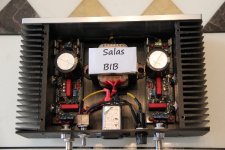
I received my little case for the BIB a few days ago and finished it last night. The box was only $20 shipped. I will miss Taobao when I leave China next year. I wish I had a nice plate to sit on top the transformer. The Chinese writing on top the old transformer looked bad.
Anyway it's has been running nicely at around 350ma per side plus the load and it's stable. Now it's time to do a little work on my headphone amp.
By the way 6.8uf wima MKS fit perfectly on the board.
I received my little case for the BIB a few days ago and finished it last night. The box was only $20 shipped. I will miss Taobao when I leave China next year.
I wish I had a nice plate to sit on top the transformer. The Chinese writing on top the old transformer looked bad.Anyway it's has been running nicely at around 350ma per side plus the load and it's stable. Now it's time to do a little work on my headphone amp.
By the way 6.8uf wima MKS fit perfectly on the board.
Attachments
Put 100uF across each rail to ground at the power receiving points in the amp to see if they will absorb some oscillation.
caps dont help much with the problem.

This is the output from the dc servo. I guess I will tweak this part and see how it goes.
Does it modulate the supply lines somehow? Maybe there on the servo to increase the decoupling uF.
fixed by increase values of decoupling caps on servo.
Thanks a lot
I bought some PCBs and mini-kits from one of Tea-Bag's group buys and have now started to assemble a pair of boards to power a Legato I/V stage.
Do I need to measure/match the transistors as per the link in the build guide if I'm using the mini-kit components?
Thanks
Ray
Do I need to measure/match the transistors as per the link in the build guide if I'm using the mini-kit components?
Thanks
Ray
Great.Let us know if it feels any better in replay after some days.
Compare to the old PSU the SSLV seems be more reserved in sound signature.
It makes the music more laid back and somehow "slower".
Overall I can enjoy the music longer and without feeling tired.
Good morning, Salas.
I'm riding shunt Shunt Regulator MOSFET V1.1.
To feed a LME49860, need +-15 Vcc, + -10mA .
I have a transformer
Compre Transformadores toroidales Transformador toroidal Nuvotem Talema, 0500P1-2-025K, Tensin 25V ac, Potencia 500VA, 2 salidas Nuvotem Talema 0500P1-2-025K en RS Online y lo recibir en 24 horas.
Of which I have 2x25Vac (500W) and +/- 37Vcc
Be feasible or better to buy one of 2X15Vac (500W) p. ahem.
("Always thinking about sound quality")
I have esperiencia, a power supply for DAC Philips CDPRO first adding a 30W transformer, and then add another 30W more, the improvement was very noticeable. So I do not want to stay low.
I have a second box for transformers.
I'll try to 100W.
* Which is more your taste, toroidal or conventional, Compre Transformadores de montaje en panel Transformador de montaje en chasis RS, 18 V ac, 100 VA, 2 salidas , Montaje en panel RS 10-5884 en RS Online y lo recibir en 24 horas..
It seems that the conventional best isolates the RF noise that toroidal ..
thank you very much and greetings
I've just completed my +/- BIB regulator pair but have to do some trouble shooting this evening so thought I would seek a steer from you guys before I start.
I've built a positive and negative pair. Target voltage is 15V. Load current is 350mA and I'm adding 135mA shunt, so total current = 485mA.
R1 on both is 6R8. Transformer is 25VA with 15V secondary. I'm using a 47R 10W resistor as the dummy load (15/47 = 320mA).
The negative supply is fine and currently steady at 15V. I'm measuring a voltage drop of 2.6V across R1 so around 380mA current. That all looks fine to me.
On the positive supply I'm getting a Vout of around 17.8V that I cannot adjust. All LEDs are lit. I'm measuring a voltage drop of 2.6V across R1 so around 380mA current, just as for the negative supply.
All passive components are identical value and type on both supplies.
I've not got the time to investigate further now (work can be so inconvenient) but will be grateful for any suggestions for where I start looking later.
Cheers
Ray
I've just completed my +/- BIB regulator pair but have to do some trouble shooting this evening so thought I would seek a steer from you guys before I start.
I've built a positive and negative pair. Target voltage is 15V. Load current is 350mA and I'm adding 135mA shunt, so total current = 485mA.
R1 on both is 6R8. Transformer is 25VA with 15V secondary. I'm using a 47R 10W resistor as the dummy load (15/47 = 320mA).
The negative supply is fine and currently steady at 15V. I'm measuring a voltage drop of 2.6V across R1 so around 380mA current. That all looks fine to me.
On the positive supply I'm getting a Vout of around 17.8V that I cannot adjust. All LEDs are lit. I'm measuring a voltage drop of 2.6V across R1 so around 380mA current, just as for the negative supply.
All passive components are identical value and type on both supplies.
I've not got the time to investigate further now (work can be so inconvenient) but will be grateful for any suggestions for where I start looking later.
Cheers
Ray
Could you post a pic? At first look it seems the problem is not related to CCS: I will check the voltage reference area.
Best
Felipe
Last edited:
On the positive supply I'm getting a Vout of around 17.8V that I cannot adjust. All LEDs are lit. I'm measuring a voltage drop of 2.6V across R1 so around 380mA current, just as for the negative supply.
All passive components are identical value and type on both supplies.
Cheers
Ray
Ray hi,
I would suspect Q106, Q105 & Q104. Measure for Vgs, Vbe.
You need to be careful with your dissipation on the CCS MOSFET IRF9530 when handling 1.7A. The power dissipated on it is going to be its voltage across, which is VDCin-VDCout, times 1.7A. Use 3 LEDs and some available value around the 0.6R 5W mark for Rset. Use 1C/W sink or better. Verify your real current by measuring voltage across Rset and dividing by its value. There are tolerances beyond the indicative chart.
~7V VDCin-VDCout is a conservative value between enough RegDrop voltage and non needed dissipation. Use just 1 red LED & 2K trimmer, in "see text" area.
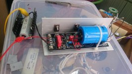
I have finally put together a pair of SSLV1.1 kit, now targeting 10-13V at 0.9 - 1.1 A
I am using:
Q101 = Q106 = IRF9530
Three green LED
R set = 0.5R
"See text" = c. 2 x red LED, R303 = 1.8K, 5K trimmer and other parts jumper.
I connected 18V AC to the board, and a 12R dummy resistor.
Upon switch on, all LED light up, no smell, no smoke, no pop....and no heat as well (except the dummy resistor)
The voltage across the dummy = 17.9V
But turning the trimmer do not have any effects.
How to locate and correct the mistake I have made, please??
Attachments
- Home
- Amplifiers
- Power Supplies
- SSLV1.1 builds & fairy tales