HI all
i have trouble understanding how to calculate value for R101 (R201,301),R103 (203,303) and trimpot R105(205,305) from BiBguide
I need it for Najda DSP, this is from Najda manual ;
Najda requires a 3-output power supply with following parameters:
+5 V recommended 1 A min 0.5 A
+12 V recommended 1A min 0.35A
-12 V recommended 0.3A min 0.25A
I have toroid with 2x15V AC which I would like to use for +/-12V
and 2x9V AC which I would like to use for +5V (one for najda, other maybe for rasppbery pi)
I don't understand how to fill excel sheet and how to read results...
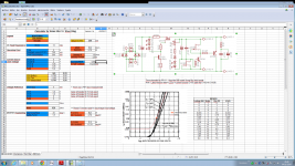
It's easy:
Input values in blue
Calculations in yellow
Results in orange
Voltage reference for 12V: "c. 10V-25V Mosfet reg. 2 1.9V LED, 1.8 kOhm R303. 5K trimmer (R105-205-305). Other parts jumper." from BiB guide.
Voltage reference for 5V: "b. 5V Vout Mosfet reg. 2 1.9V LED, 220 Ohm R303. Other parts jumper. (No need R105-205-305) " from BiB guide.
I we assume DCin 13V aprox. using 9VAC transformer, Idss of 5mA for Q103-203-303, a current source LEDs voltage of 5,9V, target operation point 5Vout, CCS 750mA and load consumption of 500mA. R101 3,9 Ohms, R103 no needed (jumper), R105 1K.
Last edited:
Tnx merlin
so I should use values under BIB guide exemples, no meter what input voltage I have and current ?
About excel sheet ;
As I have trafo with 15V AC and I need 12V with 1A
should I input ;
''DC in'' = 15V ac x 1.41 = 21V
under ''Constant current (Q101)'' = should I write 1A + 20% = 1200mA?
what should I place under ''Load Consumption''
and then I have result for R
Tnx merlin
so I should use values under BIB guide exemples, no meter what input voltage I have and current ? NO
About excel sheet ;
As I have trafo with 15V AC and I need 12V with 1A
should I input ;
''DC in'' = 15V ac x 1.41 = 21V YES
under ''Constant current (Q101)'' = should I write 1A + 20% = 1200mA? NO, 70-150mA excess on top of max load demand is usual practice for normal operation (BiB guide), so if your load consumes 1A mus be set to 1,07A max, 1,15A
what should I place under ''Load Consumption'' That's the Nadja load consumption, if you don't know exactly use a resistor between the bench PSU and the Nadja and measure real consumption with DVM with voltage across the resistor
and then I have result for R
Last edited:
Whay do you have D102 Vf set to 0 ?
(bacause you have 102B...cant use bouth at sime time ?)
I used only 3 LEDs because I don't know if your pcbs are with 3 or 4 LEDs.
Big Thanks merlin for your help and clarifications about this.
to resume
- I have PCB (back in black) which use 4LEDs
- I should measure Najda idle (not know if it's right word, not under heavy load) current to get ''Load Consumption''
- then I input values into calculator
''DC in'' = 15V ac (transformer output) x 1.41 = 21V
''Constant current (Q101)'' = 1A + (70mA - 150mA) = 1.15A
''Load Consumption'' = real (DSP) consumption in idle state - lets say that it's 500mA
And then I have results for 101 and 105 with 103 omitted.
Load Consumption only tell how much current will go on Q106 and how much power it will have to dissipate.
So I can order parts just based on DCin, DCout and Constant current ?
I have speadsheet version 1a, but I belive it's the sime as 1b that you have.
5VDC in-out always applies to keep the CCS well performing. Not that it does not work with less, but compromised.
You need a real sink, not that big L bracket only in your picture. Or bolt the bracket to a metal box with thermal paste in between.
Reg with Mosfet output goes down to about 5V, with BJT output to about 2.5V. Its all in the manual's specs.
Salas,
What might be the compromise if less than 5VDC in-out??
I may need to consider that because I may need lesser heat.
King
Big Thanks merlin for your help and clarifications about this.
to resume
- I have PCB (back in black) which use 4LEDs
- I should measure Najda idle (not know if it's right word, not under heavy load) current to get ''Load Consumption''
- then I input values into calculator
''DC in'' = 15V ac (transformer output) x 1.41 = 21V
''Constant current (Q101)'' = 1A + (70mA - 150mA) = 1.15A
''Load Consumption'' = real (DSP) consumption in idle state - lets say that it's 500mA
And then I have results for 101 and 105 with 103 omitted.
Load Consumption only tell how much current will go on Q106 and how much power it will have to dissipate.
So I can order parts just based on DCin, DCout and Constant current ?
I have speadsheet version 1a, but I belive it's the sime as 1b that you have.
For such big current remember to use mosfet Q101-301 IRF9610 for positive regulator and Q201 IRF610 for negative regulator.
It's a calculator so more or less you can trust the giving results, my advice is you will buy a couple of resistors more of each value: let's say if calculator says 100 ohms I will buy also 120R & 82R or use a trimmer and when the regulator give your target Vout & current change for fixed resistors.
BOM is as in the build guide except the voltage setting and current setting components. Those are to be selected per application. Use three green LEDS for D102 etc. jumper the fourth. Current set R101, 201, 301 10 Ohm/2W since that chip asks no more than 50mA max on any rail. For the 5V modules use red LEDS for D105, 106, 205, 206 and 500R R105, R205 trimmers. R103, 203, D101, 201 jumper. For the -15V module you will need an extra 200 designation group negative reg board section. Only change is use 5K trimmer. MOSFET type output for all sections.
Hello Aron!
Please check out this link:http://www.diyaudio.com/forums/blogs...full-kits.html. The easiest way is to buy minikits from Tea-Bag to get as many parts as possible from one source. The group buy ends this week so you have to hurry!
I have in fact built a somewhat "advanced prototype" of a 1541A DAC with Salas SSLV1.1's. You can check out the pictures on this thread: Red Baron 1541A-I2S-En begynnelse.
Regards,
VB
Last edited:
- Home
- Amplifiers
- Power Supplies
- SSLV1.1 builds & fairy tales