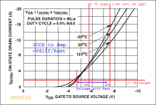
You need to be careful with your dissipation on the CCS MOSFET IRF9530 when handling 1.7A. The power dissipated on it is going to be its voltage across, which is VDCin-VDCout, times 1.7A. Use 3 LEDs and some available value around the 0.6R 5W mark for Rset. Use 1C/W sink or better. Verify your real current by measuring voltage across Rset and dividing by its value. There are tolerances beyond the indicative chart.
~7V VDCin-VDCout is a conservative value between enough RegDrop voltage and non needed dissipation. Use just 1 red LED & 2K trimmer, in "see text" area.
~7V VDCin-VDCout is a conservative value between enough RegDrop voltage and non needed dissipation. Use just 1 red LED & 2K trimmer, in "see text" area.
Attachments
It Is not stated In guide If values higher than 4.7 - 10 uF are better when using films
If I have one 4.7uF and one 10 uF which Is the right place to use
No better, bigger than 10u makes it non usefully slower. Use 10u at Vref and 4.7u in Zobel if for not very noise sensitive app.
Guys has anyone tried to turn BiBs into a lab PSU with variable Vout and V/A meters?
You need variable constant current limit and thermally/short protected low dissipation series scheme for lab psu. Slow open loop all scenarios stable. A thermal hog 7MHz shunt is no practical candidate. Get one like this.
An externally hosted image should be here but it was not working when we last tested it.
If you mean having some quality there for sonic pre-tests too, maybe for a planned top CCS limit apps range and carefully. After protos are tested electrically. But for general bench supply, checking test circuits for working electrically, biasing correctly etc. get an $100 3A automated Chinese one. Those have the utilities that speed up setting, protect, save configs in memories, carry panel meters, and turn your ears to biscuits when the fan revs up.
Various second hand Lab Type supplies come up on Ebay and similar.
They are quite robust and usually have a long life.
One or two channels and sometimes three channels of output.
Variable voltage and variable current limit with volt and ampere meters are really useful. Some would say mandatory.
They are quite robust and usually have a long life.
One or two channels and sometimes three channels of output.
Variable voltage and variable current limit with volt and ampere meters are really useful. Some would say mandatory.
No better, bigger than 10u makes it non usefully slower. Use 10u at Vref and 4.7u in Zobel if for not very noise sensitive app.
thank you for reply
what Is min recommended value for Vref
Depends on your application. If its a line stage down to 4u7 PP can sound cleaner than electrolytics, but if it is an MC phono or a sensitive digital clock with no good PSRR you would need to filter the Vref hard to minimize noise with a 220uF for instance. Its discussed in the manual.
Hi Salas,
I have built several positive and negative regulators using the recommended boards. I have noticed that the negative regulators do not have stable output voltage with respect to varying loads at high shunt currents (4-500mA through the shunt). Do I need to adjust some components or should I lower the current source to allow 100mA or so through the shunt? My load is 100mA and I currently am running 600mA from the current source.
Please advise.
Thank You,
Bill
Much spare current slips the phase margin more with the semis used in the negative polarity. Solder another 1 Ohm across the R7 to see if something changes. But first check the rail with the scope to see there is no oscillation issue giving the instability. If its a DC line without waveforms riding and lessening R7 does not help, stick a 100 uF across the sense terminals on output connector. Last resort is you try use significantly less spare current.
best film type cap that BIB can handle
I am looking to buy some films for Vref and Vout
I am struggling between Auricap and Sonicap
would you recommend which can be better to power line aplication - UGS V3
of course you can recommend some other brand
I would like to use Obbligato Gold but It Is so long
I am looking to buy some films for Vref and Vout
I am struggling between Auricap and Sonicap
would you recommend which can be better to power line aplication - UGS V3
of course you can recommend some other brand
I would like to use Obbligato Gold but It Is so long
Thank you for the recommendations Salas.Much spare current slips the phase margin more with the semis used in the negative polarity. Solder another 1 Ohm across the R7 to see if something changes. But first check the rail with the scope to see there is no oscillation issue giving the instability. If its a DC line without waveforms riding and lessening R7 does not help, stick a 100 uF across the sense terminals on output connector. Last resort is you try use significantly less spare current.
Lowering the resistor at R7 to 1/2 Ohm and then shorting it out both improved the change in voltage. Shorting out R7 was better. My current output cap is a 10uf film (C104). 100uf across the output causes the voltage change with varying loads to be insignificant. I will experiment with different output capacitors in place of my current 1 Ohm/ 10uF film Zobel.
Another possibility is to add some electrolytics to the circuit that I will be powering and leave the Zobel in place on the regulator circuit board.
My final choice is to lower the current sours down to 200 mA but I like to run it hot.
Am I on the right track??
Bill
I do. I have oscillations! I should have checked that first.
Lowering R7 makes them worse. The output cap changed to 100uF improves things but only loading the supply down so that 100 mA is shunted by the transistor makes it go away... and then the voltage is stable. I varied the output cap from 47uF to 1800uF and found 1800 to be much worse. 100uF is best.
Here are my choices as I see them:
I can now run the CCS at 500 mA, let my circuit draw 100 mA and add a resistor to draw 300 mA. Then the shunt transistor will dump 100 mA. Or, lower the CCS to 200 mA.
The other option is to build another positive regulator and use it for the negative supply by connecting the positive output to ground. I have all isolated supplies so that will not be a problem.
What do you recommend?
- Home
- Amplifiers
- Power Supplies
- SSLV1.1 builds & fairy tales