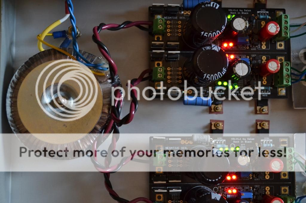
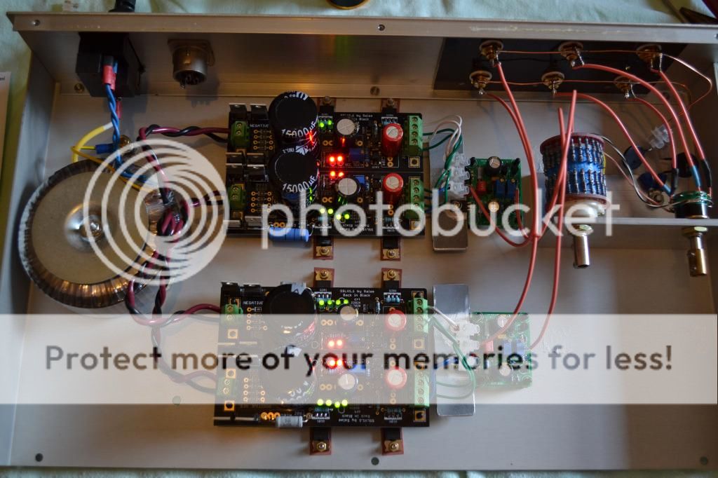
That wasn't correct. Because you had the ground side of the Kelvin in a short local point when the positive side of the Kelvin was pointed to the remote node. Its time now to be correctly implemented for the single supply if not already. If its a matter of not having a four way connector handy, the fourth wire can be directly soldered.
Hello Salas
Recently I made your V1.1 Shunt Regulator with MOSFET shunt. CSS current is 320mA, max load current is 180mA, output voltage 5V.
I tested the reg with load resistor (and without); it's stable.
Now it supplies two AK4399 DACs analog power. The wiring is as follows: First I connected analog +5V and GND points of both DACs with each other, then I connected the force and sense wires in the middle of that wire. Both Force and Sense wires are twisted pairs.
Because of the board layout, the wires cross only one DAC IC, the left channel one, on the backside of the PCB. I have random click noise on the left channel only, I think it picks up digital noise from that DAC. Is that a possibility? I already have put a 47u cap across sense wires, but it got even worse. I have no clicks at the right channel though.
Or maybe the other way around: the left DAC IC is malfunctioning being influenced by the wires that run across it.
Is there a way to make the regulator a little less sensitive, without sacrificing performance? And do you have other tips to get rid of the clicks? Thanks
Is this worth the $15 price?
Hi, sorry for the slightly off-topic question. I re-purpose the sslvs as I change projects. I know it's easy enough to put together the dummy load for testing by using serial/parallel resistors, but for $15 I was wondering if this was worth purchasing:
https://www.tindie.com/products/ara...st-affordable-dummy-load/#tab-product-reviews
They have a more industrial looking one but it's >$100USD. I think I'm buying it, but just wanted to hear your opinion on it.
Thanks.
I ordered it! Might save $15 worth of resistors if it works...Looks like a nice little tool. There is a reviews section too. I hope it won't bring a wide bandwidth shunt reg to oscillation though. $15 is worth just for satisfying curiosity I guess.
I ordered it! Might save $15 worth of resistors if it works...Thanks.
I also ordered one
I just hope that someone will not get carried away now.
An externally hosted image should be here but it was not working when we last tested it.
Problem and a couple of questions.
I finally finished putting together my boards and tested them. The negative boards seems fine but I have a couple of questions.
The load of my headphone amp is about 145ma. So I calculated the forward voltage drop of the 3 Yellow LED's which 2.06 each. That is 6.18v minus 5.2 volts (250ma) VDS? I used a 6 ohm resistor for R201 and I have about 155ma being dropped which seems right for the CCS
For the test load resistor I took 15 volts and divided the suspected load current 145ma = 103 ohm Resistor. I had a 106R and used it. Shouldn't I be seeing the 145ma from the load resistor and the 155ma load together across R201?
By the way the negative supply is running stable at 15v. I'm trying to understand it better and set it up properly.
Not VDS but VGS.
Across R201 you should see the current limit, like a lab PSU has a CC mode. The load current is deducted from that limit, its not adding up.
I suggest you lower R201 until you can find 250-300mA running through it, which is better for your load, now its running on the edge.
Across R201 you should see the current limit, like a lab PSU has a CC mode. The load current is deducted from that limit, its not adding up.
I suggest you lower R201 until you can find 250-300mA running through it, which is better for your load, now its running on the edge.
No, since you reached your goal with three LEDS it works the same, it would only make the R201 burn harder due to more Vdrop across it. Which is not good for its self noise. Four LEDS come handy in even higher mA settings where VGS rises so to have still analogous Vdrop and easier off the self R201 (or 101) value choice.
I placed a 2 ohm resistor in there and it's sitting nicely at 295ma thanks for the help.
Now for the problem. My positive regulator powers up fine LED's all light and no smoke. But I can't adjust it to over 14.6v. The current across R101 is still around 140ma with the 6 ohm resistor. I will drop it down to 2 ohms when I figure out the regulator problem.
I was going to start checking all my voltages on the FET's and transistors after I give the negative supply some burn in time. Possibilities?
Last edited:
That did it. I drop the R101 to 2 ohms and it worked fine. It's running at about 275ma so I will need to tweak the resistor value to get them running at the same point but that's pretty easy. I thought it was going to be a bigger problem. Your a great resource here. Thanks so much.
I'm looking forward to trying these out on my headphone amp.
I'm looking forward to trying these out on my headphone amp.
- Home
- Amplifiers
- Power Supplies
- SSLV1.1 builds & fairy tales

