Used lytic 220uF as Vref & lytic 47uF for Zobel without R but jumpered as per SSLV1.1 BiB guide
What do you want?
to change Zobel Lytic
to add 100uF lytic across sense+ & sense-
Can I use non polar?
to change Zobel Lytic
to add 100uF lytic across sense+ & sense-
Can I use non polar?
Last edited:
First add 100uF across sense as it is. Non polar is OK. Then try Zobel MKT+R in case its still fuzzy if that lytic now there has a problem. But leave the one across sense.
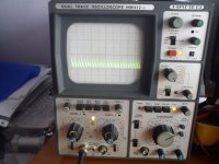
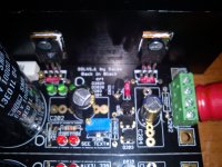
Left channel negative rail with onlye 100uF BG NP added
Attachments

Last edited:
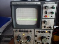
Right channel negative rail with only 100uF BG NP added
Attachments
Last edited:
Still problematic.
Merlin, do you have 270R for sure in gate stopper place (parallel on board near the input & output Mosfet pins)? Or something different value by any mistake? Some used before heated cap many times with iron? Because you should have simple line like in your positive pic no problem at least with dummy test.
Merlin, do you have 270R for sure in gate stopper place (parallel on board near the input & output Mosfet pins)? Or something different value by any mistake? Some used before heated cap many times with iron? Because you should have simple line like in your positive pic no problem at least with dummy test.
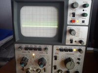
Just did a quick test on a JC2 pre I am doing some tests with.
Negative supply is a flat line with a 20MHz scope set to max.
Probably something is wrong with a resistor, as Salas mentioned. I shouldn' t look at the caps.
Negative supply is a flat line with a 20MHz scope set to max.
Probably something is wrong with a resistor, as Salas mentioned. I shouldn' t look at the caps.
Attachments
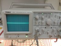
That's the proper line, even on real active circuit load.
What was the vertical (volt/div) knob's position George?
What was the vertical (volt/div) knob's position George?
Still problematic.
Merlin, do you have 270R for sure in gate stopper place (parallel on board near the input & output Mosfet pins)? Or something different value by any mistake? Some used before heated cap many times with iron? Because you should have simple line like in your positive pic no problem at least with dummy test.
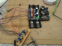
Measured all four gate resistors 270R in the negative rail and all four measure 270R, attached pic right channel negative rail
Attachments
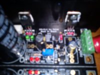
Looks typical except for rather long Mosfet legs. Still something wrong is going on either parasitic or component wise. Put 1R instead of jumper to see what it responds to us. If still fuzzy, then C204 MKT.
Measured with DMM rest of resistors and are ok in both negative regs, R208 47R & R204 1R
Transistors, Jfets, inspected for proper type proper place odd mistake too?
- Home
- Amplifiers
- Power Supplies
- SSLV1.1 builds & fairy tales