look at simulation last page In BIB - there Is not much difference between MOSFET and BJT regarding flat Zo
that Is why I ask If there are people with analyzer to take a noise vs freq curve within 1 Hz to greater than 100 KHz
that Is why I ask If there are people with analyzer to take a noise vs freq curve within 1 Hz to greater than 100 KHz
Salas I forgot to tell you that the NP D1 I/V only sounded with voice without presence or deep with the BiB and when I increased the volume I heard a little of hum, whit LM317 + LM337 sounded good no hum, any idea what happens? I tried 10uF MKT & 220uF lytic as Vref also zobel 10uF MKT+1R & zobel with 47uF lytic & without R?
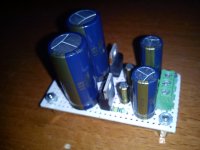
Attachments
Don't know, it can be the wide PSU bandwidth not helping the particular circuit. Any PSU is in the total current loop. Use whatever helps better a specific circuit. I don't know the analysis of the particular one to speculate more, not familiar with it. Hum beyond ground loops or ripple is also a sign of instability many times. Its either you can fully scope it and measure it and compensate it to play great with this reg or just skip it if it demands beyond simple experiments with parts you feel confident to perform. Or you can persist on trial & error.
As I said its how you interface something with what, and to do it well in odd cases you need engineering data. That's life, no worries.
I'm worried because isn't for me is for a friend who a spent a lot of money buying two R-Core, the pcbs, the components, the heatsinks, my work not because is my friend so it's free.
Salas a capacitance multiplier from Elliot Sound (attached pic) can be a good idea? the pic is for +-20Vout & I need +-15Vout Elliot said can be reach reducing 12K resistor.
P.S. thanks for help.
Salas a capacitance multiplier from Elliot Sound (attached pic) can be a good idea? the pic is for +-20Vout & I need +-15Vout Elliot said can be reach reducing 12K resistor.
P.S. thanks for help.
We are not allowed by Elliot to host esp schematics or encouraging copying them without permission, sorry.

I'm sorry, I understand you delete the pic.
You don't have any other capacitance multiplier schematic?
You don't have any other capacitance multiplier schematic?
I'm worried because isn't for me is for a friend who a spent a lot of money buying two R-Core, the pcbs, the components, the heatsinks, my work not because is my friend so it's free.
P.S. thanks for help.
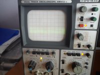
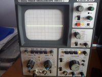
Put your scope on the reg to I/V power rail in ac mode input and post a picture. If its a matter of bad interfacing it should show weird patterns or spikes instead of simply a line. In general if so, a 100uF cap across sense only locally on the reg, kills it.
I'm sorry, I understand you delete the pic.
You don't have any other capacitance multiplier schematic?
You can use from the phono pre pre schematic but with proper voltage chip regulator input block for your case.
Put your scope on the reg to I/V power rail in ac mode input and post a picture. If its a matter of bad interfacing it should show weird patterns or spikes instead of simply a line. In general if so, a 100uF cap across sense only locally on the reg, kills it.
The scope I will try to do it. The 100uF cap across sense only do you refer the cap connected the positive leg to sense positive & negative leg to negative sense, right?
You can use from the phono pre pre schematic but with proper voltage chip regulator input block for your case.
I have it, I will do a look, thanks.
Put your scope on the reg to I/V power rail in ac mode input and post a picture. If its a matter of bad interfacing it should show weird patterns or spikes instead of simply a line. In general if so, a 100uF cap across sense only locally on the reg, kills it.
Left channel thin line positive rail big line negative rail
Attachments
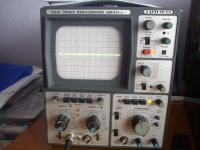

Salas I'm sorry for the bad measurement is the 1st time that I use the scope so I need guidance thank you for your patience.
Thanks George could you check that the scope is in the right position to do the AC measurements?
Thanks George could you check that the scope is in the right position to do the AC measurements?
It must be the button on the lower right of the scope and is set to AC for the left channel - the one you use - so it looks OK.
I would put the negative on the scope with a dummy load to see if you still have oscillation. If no, then you should look further down, maybe your cabling or something.
- Home
- Amplifiers
- Power Supplies
- SSLV1.1 builds & fairy tales