I have a cheap little reverb tank that I'm trying to turn into a 'guitar pedal' but now it is having some probs. Earlier on the breadboard, the tank did work.
On the coils, I'm currently measuring 46ohms (DC) across the tank's input and 156 ohms on the output, so they are not 'open'.
I have a TL072 sending signal just fine to the input coil. And the other half of the IC is picking up the output just fine (if you shake the springs by hand, using my audio probe).
But, I am not getting any of my input signal coming through the springs.
Visual inspection and continuity checks all seem to be ok.
I tried direct-injecting a 'headphone' output from a cassette deck straight into the tank, same story.
This is the schematic (Blues Junior) I've been basing it on:
https://www.tubesandmore.com/sites/...er/img/spring_reverbs_fender_blues_junior.svg
And the page it comes from:
https://www.tubesandmore.com/tech-articles/spring-reverb-tanks-explained-and-compared
Any suggestions for how to further trouble-shoot would be greatly appreciated!
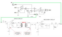
A couple things I didn't mention - I've spliced that circuit with this 'blending' circuit (attached), which comes from here:
https://sound-au.com/articles/reverb.htm ("input and mixing stages").
The green lines show how I've connected the two circuits.
Also - I am wondering if I have the impedance all wrong going into the tank - at 46 ohms DC that's about 330 ohms impedance on the input, but this schematic is for 800 ohms input.
Attachments
Heh, well I have gotten the springs to vibrate while on the breadboard, but I guess something got lost in the translation to the circuit board! I've tested voltages and they're good, so is continuity.
Correct, I tested DC voltage at both chips and V+ / V- are solid at 15v/-15v.
Tested the input and output of the tank terminals with an ohm meter, so that's going to be DC resistance (and not AC / impedance).
Test equipment - I have a couple of multimeters, but I'm thinking I need to bust out my oscilloscope and fix my Heathkit signal generator soon! 🙂
(and my little audio probe going into a practice amp!)
Ok, a scope will make this much easier.
If you can't get the generator fixed soon, maybe you can use a generator app on your phone.
All you do is connect an input to the NE5532 (less than 0.1 V signal), and follow it through the circuit.
At the point it is gone, the problem is just before there.
If you can't get the generator fixed soon, maybe you can use a generator app on your phone.
All you do is connect an input to the NE5532 (less than 0.1 V signal), and follow it through the circuit.
At the point it is gone, the problem is just before there.
Thanks, Rayma.
Yeah, i'll get that scope out (I am just pulling my gear out of 14 years of storage and setting up my bench!) and use a phone sig gen for now.
By the way, the NE5532 seems to be working fine when I poke it with the audio probe. The tank problems are closer to the TL072.
What's odd is that I am getting input signal at the tank input, and the springs when you hit them at the output, and I have resistance on both the input and output coils of the tank (so, they're not open), yet, no audio is making it from one side of the tank to the other. I'm really starting to wonder if this input coil went out on me, but it seems to test 'ok'.
Am I interpreting correctly: the bottom of both input and output coils appear to be tied together by the shield? If this is the case, the bias scheme to the driving opamp can't work.
Maybe connect driving opamp to inout coil via a blocking cap? Arrangement of attenuation at driving input with subsequent gain from opamp seems a bit clumsy.
Maybe connect driving opamp to inout coil via a blocking cap? Arrangement of attenuation at driving input with subsequent gain from opamp seems a bit clumsy.
Surely the two transformer return wires are not connected together.
But if they are, that would be bad.
But if they are, that would be bad.
Hey BSST, thanks for chiming in!
No, the input coil and output coil are not tied together via shield. The input coil's 'negative' half doesn't go to ground. It 'should' be just like in the schematic - except I have no shielded wire in there yet.
Yeah, if the two circuits seem mixed together in a clumsy way, that's all me - I'm just trying to hack these two circuits together.
I did try going straight from a pre-amped headphone out direct to the tank input, but no luck.
I'm guessing its the darn coil, or maybe I'm just not driving it hard enough (and/or impedance issues)?
Time to be pro-active about setting up test gear! Thanks for the kick in the tail, Rayma!

No kidding! Yeah, the Tektronix T935a. I got it just before I had to put my life in storage and leave the country, so I am just now learning this thing!
Since the input coil is isolated, I suggest grounding its lower end. You'll get a bit more power by not driving through the 47 ohm resistor. Maybe make the 910k a jumper instead. The 330pF may be too small...
hey thanks BSST.
so, you're saying to ground the lower end of the input side of the coil instead of it heading back to the inverted input of the first opamp? cuz i think i did that accidently before and nothing worked (laughs on me!). i must not be understanding what you mean.
next up, you're saying jumper the 47ohm, and also the 910k (1M on my build)?
and, increase the 330pf? ... i'll try out a .1uf or so.
No, I'm suggesting making the 910k resistor = 0. Other parts are OK. Drive the coil from opamp out to ground. 0.1uf sounds good. Driving opamp will have gain of about 101 (1+4.7k/47), probably more than you'll want.
Have fun!
Have fun!
Right - so I mean 'jumper' the 910k (so, its bypassed). Right?
"Drive the coil from opamp out to ground" - Do you mean take the bottom of the input coil and go straight to ground with it?
Fun for sure! Thanks for the help.
"Drive the coil from opamp out to ground" - Do you mean take the bottom of the input coil and go straight to ground with it?
Fun for sure! Thanks for the help.
- Home
- Amplifiers
- Solid State
- Spring Reverb Circuit Problems