Just like conductance is current divided by voltage (the reciprocal of resistance),I must admit, I have no idea what transconductance is, I just looked it up and I still don't.
transconductance is the output current divided by the input voltage.
And similarly transimpedance is output voltage divided by input current.
Not sure why its not called transresistance (or why transconductance isn't called transadmittance) - seems a bit inconsistent.
hi Mark, thanks for taking the time to explain that. So, how is this circuit doing that, and what is the issue with it, typically?
I just stumbled on this thread...
Spring reverbs need about 100-300mW to be driven correctly, that s the power required for Accutronics models,
depending of the size, also the signal should be cut off with a basic high pass filter such that only frequencies
that produce the reverberation effect in natural spaces are driving the spring, this can be set by adapting the input
or/and output capacitors of the power amplifier to the relevant value(s).
hey wahab, thanks for the input. a variable high-pass filter would definitely be a good addition.
Just reviewing the previous posts and JMFahey already mentioned this, so I'm going for it.Add a 10-15 ohm 2W resistor in series with input coil, leave the rest of the reverb circuit as-is.
There s no need of something complicated, just use the amp input capacitor to limit its power in the lower
range so there will be no distorsion at all and more dynamics, and do the same with its output capacitor,
since both provide a 6db/octave cut off below 400-1000Hz (exact frequency is to define experimentaly) that will
provide a 12dB/octave total cut off and is way enough.
range so there will be no distorsion at all and more dynamics, and do the same with its output capacitor,
since both provide a 6db/octave cut off below 400-1000Hz (exact frequency is to define experimentaly) that will
provide a 12dB/octave total cut off and is way enough.
thanks wahab. yeah, this is going in a multi-effects unit (all patch-cable analog) that has HP/LP/BP filters in it, but i wouldn't mind adding a pot for HP directly to the spring verb unit. sounds very useful and frees up a filter.

Greetings Gonecat, i also have good US friend in France where i m living most of the time.
BTW, i m just about to mod the spring reverb of my old Ibanez EQ100 guitar amplifier in the coming days, they implemented
such a high pass cut off but it s done at a too high frequency, something like 3-4KHz, and the reverbered level is very low, that was
one of the main factory mistake in this amplifier in the first series, although i have an Alesis and a Yamaha digital reverbs spring reverbs have an unimitable vintage flavour.
You don't want to make that frequency variable? Sometimes you just want some nasty bass in your spring reverb signal!!
Where in France are you? I lived there many years.
Where in France are you? I lived there many years.
Not sure about your particular amp (should check its schematic) but often Japanese makers just used low impedance tanks (say 1 ohm or so DCR, 8 ohm nominal impedance) driven from a small chip amp, call it "car/TV type" if you wish, meaning it was nothing special.Greetings Gonecat, i also have good US friend in France where i m living most of the time.
BTW, i m just about to mod the spring reverb of my old Ibanez EQ100 guitar amplifier in the coming days, they implemented
such a high pass cut off but it s done at a too high frequency, something like 3-4KHz, and the reverbered level is very low, that was
one of the main factory mistake in this amplifier in the first series, although i have an Alesis and a Yamaha digital reverbs spring reverbs have an unimitable vintage flavour.
Yet those reverb systems "worked". 🤷🏻
I have it wired up but it just chirps at a regular interval of around one-per-half-second; banging the springs makes it go underwater, and the 5w resistor gets real hot real quick. I have the + of the TDA2030al chip wired to +15v and pin3 is going to 0v/ground on the circuit (in the PDF linked here it has schematics showing pin 3 going to both 'ground' on one circuit and '-v' on another circuit and i tried both, but when I check voltages they just bounce all over the place. When I double check my power supply by itself it is solid +/-15v. I chopped off the legs of pins 1, 2 and 3 on the first opamp and wired their abandoned leads over to the power amp chip. I'm just going thru the circuit line-by-line now trying to find the fault, but ideas for troubleshooting are always welcome, of course
JMFahey, that s an Ibanez EQ100 from the late 70s that i bought used, the reverb amp use two transistors in serial and both in common emitter like the old RIAA or mic preamp schematics, the second transistor has a high current with the collector loaded by a transformer whose secondary drive the spring reverb, a very unusual circuit, they replaced this weird arrangement with a small IC in the early 80s.Not sure about your particular amp (should check its schematic) but often Japanese makers just used low impedance tanks (say 1 ohm or so DCR, 8 ohm nominal impedance) driven from a small chip amp, call it "car/TV type" if you wish, meaning it was nothing special.
Yet those reverb systems "worked". 🤷🏻
You don't want to make that frequency variable? Sometimes you just want some nasty bass in your spring reverb signal!!
Where in France are you? I lived there many years.
I m in east France in the Alsace region, at 20km distance from Germany, that s practical since some electronic items are cheaper in Germany with vroaderr choice, but food is of much better quality in France and germans often shop some food by here.
As for the circuit you used beware that the TDA2030 is a powerfull and oversized driver, using a symetrical supply
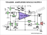
is risky because in case of failure the spring could be fed by a continuous 15V voltage destroying it, indeed even if this amp work there is surely an output DC offset that eventually could saturate the spring s input transformer with a relatively high current, it would be eventually more cautious to use it with an assymetric 15V supply like in the schematic below and a 100-330uF output coupling capacitor, this schematic is also in the datasheet PDF you linked.
Attachments
Thanks a lot for the insights, Wahab.
So, am I cool to run this from the +15v and 0v (ground) of my dual supply, with the 5w resistor and the big cap in series?
Alsace is amazing, I've been through there several times. I was mainly in Nice (my favorite city to live in the world!), Paris and Orleans.
So, am I cool to run this from the +15v and 0v (ground) of my dual supply, with the 5w resistor and the big cap in series?
Alsace is amazing, I've been through there several times. I was mainly in Nice (my favorite city to live in the world!), Paris and Orleans.
Aren't (small) power opamp chips like TDA2003, TDA2030 and the like some bit of overkill for this purpose?
Best regards!
Best regards!
Couldn't resist 🙂
So, hell if I know, Kay! That's why I'm here, to learn and hopefully figure out how to get this running. I appreciate everyone's input.
What I've gleaned so far is that opamps won't power this 8ohm load and that these small power amp chips are what's needed.
If the tank is indeed a lot lower impedance than what most people are used to (esp. tube builders), then you do need a chip amp. It likely still doesn’t need a lot of POWER, so a 12 volt chip is probably enough. LM386 doesn’t really like 8 ohm loads. Drives 16-45 ohm just fine but struggles with a “real” speaker. LM380 ought to work, if you don’t need or want to use current drive. But I didn’t think they were even making those anymore. Went away with 80’s boom boxes.
thanks for the input, wg_ski. so are you saying this TDA2030 isn't the right choice / can't be made to work in my reverb labor camp?
Thanks a lot for the insights, Wahab.
So, am I cool to run this from the +15v and 0v (ground) of my dual supply, with the 5w resistor and the big cap in series?
Alsace is amazing, I've been through there several times. I was mainly in Nice (my favorite city to live in the world!), Paris and Orleans.
A 470uF output cap is more than enough here, and on a 15V single supply a TDA2030 has barely 3W/8R power at 10% distorsion,
so a 8-10R resistance in serial would bring down the max power driving the spring to something like 0.7W, in principle that should be enough without risking endangering the device, this way the serial resistance doesnt need to be that big, a 2W one is sufficent, you can eventually test a higher value in a 15-22R range to check if it s enough.
This is of course assuming that the spring has a 8R impedance, wich is the usual value in most Accutronics devices.
As for the OT Alsace is a really cool region, there s a various landscape with some nice mountains and the proximity
of a lot of european countries on top.
- Home
- Amplifiers
- Solid State
- Spring Reverb Circuit Problems