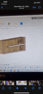
@Brian Steele I would like to ask if there is a chance to make a spreadsheet of the classic TL cabinet, as in the attached picture? For example, based on the MLTL3 spreadsheet.
Attachments
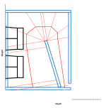

Ok, that wasn't too difficult to do. I've only implemented one of the options however, as the other should produce the very similar results as the vent is just shifted from the back to the bottom. The latest version of the workbook is now v.14 I also updated a few of the routines and corrected a minor error in the layout of the path.

I added a few minor updates to the BOXPLAN-MLTL3 workbook, as I wanted to include a few more ideas, i.e.
1. Instead of using Front Area / Vent Area to figure out the size of the vent, I redid the calculations to use the desired taper ratio for the TL instead. I used S1/S5 to define the taper ratio, but I think I might change it to S1/S4 in the future, as the section L45 (the "vent") is basically a constant CSA section.
2. I moved the S4 position closer to S5, and calculating the length of the port panel (for the Option 1 layout) is now included in the optimization routine. This results in a slightly smoother expansion graph.
3. The workbook can now model constant-expansion TLs with the folds illustrated in the workbook. Just set S1/5 to 1 and Optimize. There seems to be a minor error with the constant expansion optimization routine though. It can't seem to reduce the errors to zero. The error is VERY small though, and I doubt would make a difference to the predicted output. Still a bit annoying though, and I might have another look at the calculations in a day or two.
Right, vent S4-S5 should be the same CSA and L45 should = 1.905cm (0.75in) 19.05 mm or whatever thickness of wood used.
Fixed. Optimization for a constant taper no longer shows minor errors...

will a cyclops box tend to hit lower than say the para2? also would the cyclops be less directional and spread more? ive had success with the para2 but just seems over all that box design would be much better for 40-80. What boxplan is going to be the best for 20-40? i can build a 6th order that will smash those notes but really trying to get a paraflex enclosure to do the same for the extra output and clean ness of the sound. any suggestions? maybe im going in the wrong direction?
If you want a parallel tuned to 20 hz, mate a 4 meter resonator with a 4/3 meter resonator. if the response is too peaky extend the series exit out in horn response
Also I’m not sure what you mean by 4 meter resonator with a 4/3 meter resonator. Maybe u could draw something out. It’s hard to vision what you mean as everyone calls something different or does something different.
Those resonators are:
4 meters (1/4 resonance)
1.6666 meters (3/4 resonance)
and 0.8meters (5/4 resonance)
You want to merge 3:1 resonators in qw (harmonics) otherwuse you have other resonances Or cancelaction after the 3/4 seen in the simulation details and random junk, ringing, etc..
Here’s 2 b/c 18s simmed in a 300cm/100cm for an excellent example. I’ve done this with a few drivers 4”-12” and it’s not too shabby.
put that simulation into wizard and change the size of the 100 cm resonator back-and-forth to observe the issues. Or resize it a lot bigger than the other sides, cross-sectional area, and discover the same type of misalignment starts to occur. Or change the driver position and observe further issues..
This plagued many paraflex models(especially in a room or car ) in the past . it’s way too hot up top and has phase issues prior to that area of Resonator overlap(? Not a great speaker with those issues?)
its super intersting in a similar way offset driver is in a TL.
Attachments
Last edited:
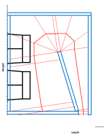
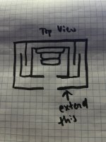
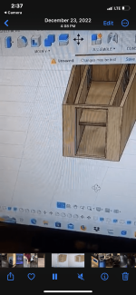
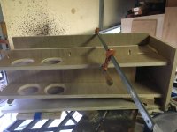
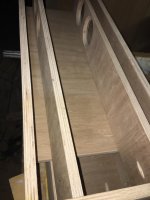
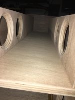
So you’re saying extend that part into the rear chamber more to level it off so it would end up looking something like this instead of flush like in box plan?
this same layout pattern has worked REALLY good for me in a variety of drivers and sizes. the impedance plot matches the sim, etc(ive never measured it with the exit (L45 @50cm)waveguide added in the B/C sim)
Simple (everything is the same legnth) so, 3x and 1x. Off the front and rear of the cone(s).
Attachments

The B&C is the 18TBX100??Those resonators are:
4 meters (1/4 resonance)
1.6666 meters (3/4 resonance)
and 0.8meters (5/4 resonance)
You want to merge 3:1 resonators in qw (harmonics) otherwuse you have other resonances Or cancelaction after the 3/4 seen in the simulation details and random junk, ringing, etc..
Here’s 2 b/c 18s simmed in a 300cm/100cm for an excellent example. I’ve done this with a few drivers 4”-12” and it’s not too shabby.
put that simulation into wizard and change the size of the 100 cm resonator back-and-forth to observe the issues. Or resize it a lot bigger than the other sides, cross-sectional area, and discover the same type of misalignment starts to occur. Or change the driver position and observe further issues..
This plagued many paraflex models(especially in a room or car ) in the past . it’s way too hot up top and has phase issues prior to that area of Resonator overlap(? Not a great speaker with those issues?)
its super intersting in a similar way offset driver is in a TL.
I know this is probably a dumb question but just so I know should I be reversing polarity with these boxes since the sub is inverted? I’ve always wondered that? 🤔
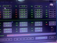
That is a very nice frequency response there unfortunately I’m just not getting what ur saying, I never do and it’s frustrating lmao 🤦♂️
Ds115-4The B&C is the 18TBX100??
Attachments

Basically, it's a 10-foot (304.80cm) stepped tapped horn (BP6S) that acts like a BP6P because S3-S4 and S4-S5 exit together instead of S3-S4 exiting into S4-S5 like a normal tapped horn(TH).
10 foot is kind of the magic length for TH's. My home theater subwoofer is 10 foot negative flare TH or Tapered Tapped Quarter Wave Tube or Pipe (T-TQWT or T-TQWP).
TH = positive flare = loud & big.
TQWP or TQWT = straight flare = easy build (no angles).
T-TQWT or T-TQWP = negative flare = low & small.
Hofmann's Law = loud, low, small...pick 2.
I get that but none of that answers my question that was in general about the cyclops box plan vs para 2. I can make them bigger and get lower all that jazz just seems maybe there is a better suited type of paraflex. Also when I changed the polarity it sounded way better haven’t got to turn it up turn it up yet tho so that’s not for sure
- Home
- Loudspeakers
- Subwoofers
- Spreadsheet for Folded Horn Layouts...