Os, NFB ground return is going to the decupling ground. You can see that in the post #15, R37 (four of them) via R9 going to the decupling ground and decupling ground is connected to the main ground via R0.
Oh , yeah . You showed that example. I see , your signal ground is my G1 and your cap ground is my G2. R9 goes to the signal gnd. and R0 is my Rlift
connecting to the cap gnd. (decoupling). your NFB takeoff point is also correct. What is your speaker ground ??
As I understand it , NFB is referenced between the takeoff point and the exact point of where the current from the loudspeaker returns to it's star path.
I have the Wolverine layout , but it is VFA.
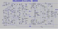
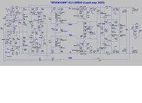
Edit , here is the G1/G2 schema ... I added jumpers (solder bridges) to the IPS ground traces so you can connect to either "G"s.
I want it to really perform as simulated ... below.
OS
connecting to the cap gnd. (decoupling). your NFB takeoff point is also correct. What is your speaker ground ??
As I understand it , NFB is referenced between the takeoff point and the exact point of where the current from the loudspeaker returns to it's star path.
I have the Wolverine layout , but it is VFA.
Edit , here is the G1/G2 schema ... I added jumpers (solder bridges) to the IPS ground traces so you can connect to either "G"s.
I want it to really perform as simulated ... below.
OS
Attachments
Last edited:
I have two possible loudspeaker ground connections, one in the middle of the ground line, close to the loudspeaker output connection(by the way I do not put the output inductor on the board any more), and common power ground connection.
Have you seen my type of a compensation, I called it IOTPC, very suitable specially for CFA? Very stable.🙂
https://www.diyaudio.com/community/threads/oitpc-output-inclusive-tpc-not-tmc.317335/
Have you seen my type of a compensation, I called it IOTPC, very suitable specially for CFA? Very stable.🙂
https://www.diyaudio.com/community/threads/oitpc-output-inclusive-tpc-not-tmc.317335/
I read that thread , I remember it was one of the first that sparked my interest in CFA FB. It would be rather easy to apply IOTPC to this Hellraiser.
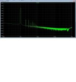
As you see , I'm not too bad without it (.0006% / 4R - 20Khz),
Next version ?? Hellraiser V2 ?
Just want to put some miles on this basic version , most would likely not notice 6PPM to .6PPM ?
Also , those SMD silver's are very expensive - would I spend +20 dollars for sub-PPM ??
OS
PS - next post it will be DONE ! My first SMD layout...
Attachments
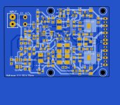
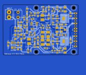
They make 10uF MLCC in 1206 these days, you don't have to use electrolytics.Wahhh ! had to go bigger (50 X 70mm) - below. See C3 /C4 , they equal - https://www.mouser.com/datasheet/2/212/KEM_A4070_A765-1101579.pdf
Nothing but the best for my regulators.
It's DONE ! Servo uses a dual (super cheap-.60c) BA4580 MSOP or SOIC-8. Ground one channel as a follower - all done .
Must OCD on the design and port the finished "blocks" to the spooky. The VAS,servo, and input is the same. The Spooky will
use 4 of those matched MSOP-6's for the cascodes/LTP's , easy.
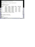
3'nd pix is what a whole amp package will look like. 105W @ 8R and .003% worst case THD in a small package.
Power supply PCB and Spooky is next.
OS
Must OCD on the design and port the finished "blocks" to the spooky. The VAS,servo, and input is the same. The Spooky will
use 4 of those matched MSOP-6's for the cascodes/LTP's , easy.
3'nd pix is what a whole amp package will look like. 105W @ 8R and .003% worst case THD in a small package.
Power supply PCB and Spooky is next.
OS
Attachments


I jumped ahead , WOW ... that's exactly what I did. They even have 1206 or 2512. MLCC ceramics would be good for decoupling the zeners ???They make 10uF MLCC in 1206 these days, you don't have to use electrolytics.
OS
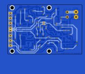
Vias on the pads of components aren't a good idea. They suck up solder if you are using stencils and baking the board, which is the easiest way to assemble it.
I was wondering that... thanks. Any ideas on how to get it done ?? ... you see how many I have. If I do have to relocate all them vias , how can i make them
soldermasked ??
Back to the drawing board. Wish i knew this a few days ago !!
OS
soldermasked ??
Back to the drawing board. Wish i knew this a few days ago !!
OS
I was wondering that... thanks. Any ideas on how to get it done ?? ... you see how many I have. If I do have to relocate all them vias , how can i make them
soldermasked ??
Back to the drawing board. Wish i knew this a few days ago !!
OS
You can have Via in Pad epoxy filled and capped (plugged and capped) - it do however add a bit of cost to the PCB.
Yes, At JLCPCB they have this page describing it:
https://jlcpcb.com/help/article/122...Plugged,-Epoxy-Filled-and-Copper-epoxy-filled
In the Ordering formula:

However, at JLC at least, it adds quite a bit of cost. For a run of 25 PCBs it adds 61 USD.
https://jlcpcb.com/help/article/122...Plugged,-Epoxy-Filled-and-Copper-epoxy-filled
In the Ordering formula:
However, at JLC at least, it adds quite a bit of cost. For a run of 25 PCBs it adds 61 USD.
Plugged vias are an option but not really needed. There minimal current flow in an input stage. The plate through is fine there. If you want to fill them you can specify uncovered vias.
Is there a way to cover the via with soldermask ? I have seen this on PC and other SMD boards.
I assume (don't like doing that) if a board was "ovened" or wave soldered .... any via would still fill with solder even if it
was outside of a pad area..
OS
I assume (don't like doing that) if a board was "ovened" or wave soldered .... any via would still fill with solder even if it
was outside of a pad area..
OS
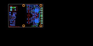
Good !! The "soldermask" button on sprint allows to deselect any group of vias , covering them. Doing JW's correction is not
as hard as I thought, 😎
OS
as hard as I thought, 😎
OS
So including the via soldermask info in the gerber won't give you a "tented via" ?
My last attachment shows the vias covered ?
OS
My last attachment shows the vias covered ?
OS
Now for my "baby" - I love the spooky !!
This will be the finest artwork to date !!
Crazy , anal , symmetrical perfection. AND , I can use all matched pairs for it's "heart".
I actually have one of these running me BASS ! 8 years of constant duty. KRK V12HO 500W woofer + SKAR audio SPL box tuned to 32hz !!!
Rattles the whole building !
OS
This will be the finest artwork to date !!
Crazy , anal , symmetrical perfection. AND , I can use all matched pairs for it's "heart".
I actually have one of these running me BASS ! 8 years of constant duty. KRK V12HO 500W woofer + SKAR audio SPL box tuned to 32hz !!!
Rattles the whole building !
OS
Attachments
- Home
- Amplifiers
- Solid State
- Spooky and Hellraiser SMD 60W amps (Wolverine compatible IPS)