1audio said:However its the RC ratio that matters. All the caps in are in series and the resistors are in series. Probably would not affect things to model them as separate strings instead of as a ladder. The result is that the reactance of the caps follows the resistance of the resistors EXCEPT for the external stray aspects. And those can be significant in the layout.
Hi Demian,
Any idea how large the external stray capacitances are, i.e. from resistor to resistor and from resistor to the ground plane?
Cheers,
Edmond.
You need to look at the specific layout to work out those details. Anywhere from 1 pF to 15 pF is possible. The advanced PC layout programs can get some of that for you. I would just build it and test to see where I would add trim caps and what values I would use. I would probably end up with a piston trim cap across the feedback to ground resistor. The calculations would be like this- input cap of feedback input, figure 10 pF at a guess. Gain 20 dB (simple arithmetic) so the resistor ratio is 9:1 and then the ideal would be around 1 pF across the resistor array. Not likely. So the trim cap is across the feedback to ground resistor. In practice the caps would all be bigger and the compensation enters into the picture.
Brings up an interesting question- what gain should a preamp line stage have? In the past 12dB to 20 db was about right but today is seems 6 dB is too much. Same for power amps and phono/mike amps. THX has a 30 dB (I think) standard for amps, based on a standard sensitivity for speakers etc. Is this relevant to high end audio?
Brings up an interesting question- what gain should a preamp line stage have? In the past 12dB to 20 db was about right but today is seems 6 dB is too much. Same for power amps and phono/mike amps. THX has a 30 dB (I think) standard for amps, based on a standard sensitivity for speakers etc. Is this relevant to high end audio?
Ladder network
Hi Demian
I've simmed a typical FB ladder for a power amp, comprising 30 resistors of 100 Ohms. I've 'put' them side by side. The parallel capacitance poses (of course) no problem. The 'intra' capacitance, the stray capacitance between adjacent caps, neither. It's the stray capacitance to ground that poses the greatest problem. If the latter is 10pF (per resistor), then the phase shift at 1MHz amounts to 50 degrees, far too much. If 3pF, I get 16 degrees. Still too much. So, can we get it down to 1pF?
Cheers,
Edmond.
As you can see its about technique and tricks. I would first look at flying the array 2 CM above the board to reduce the capacitance. But that creates a window for EMI pickup and who knows what else.
Are you modeling the stray capacitance as a single cap from the center of each resistor to ground? (similar for the other parasitics?)
Have you measured or calculated the capacitance or just guessed (like I would)? How big are the resistors? Its a distributed effect so the curves won't be the usual 6 db per octave, they will increase with frequency.
You could make a tall sub board (30 1/2" resistors in series would be a loop 15" or 2 loops 7.5" highwith a small window and less capacitance to ground, unless it gets close to the top of the case.
I know its solveable- the Tek P7015 is good for 75 MHz with 100 Mohms in and 1 MOhm out P6015A Specs and it uses two resistors about 5" long with a shunt capacitance.
Perhaps the trick would be to contain the resistors in a shield tied to the input (low Z source) and a shunt cap at the FB to ground to compensate for the shunt cap from the input. Eliminates the stray cap to ground. Can be done with a copper plane directly below the resistor array with a window around the last resistor. (I did something similar in the NuForce preamp.)
I'm lobbying for a new "feedback divider" thread rather than going so far off topic in the Spice thread - could a mod move these posts?
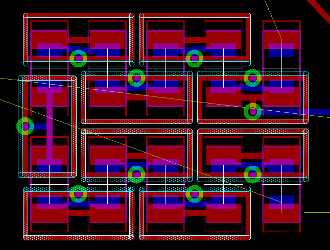
I have built a board with a equal value R string feedback, but with added 2nd low impedance "guard" string on the bottom of the board which drives guard rings for the feedback string PCB pads/nodes
pcb trace shield/guard rings are usually seen as a ultra high impedance/low leakage technique but it can also work to higher frequencies "bootstrapping" parasitic C for very low effective parasitic C, and when you consider typical pcb epoxy with fire retardants and adsorbed mositure is a poor dielectric then sub ppm distortion divider may want to use these techniques
the pic is just the top/bottom, guard ring top trace seen with overlapping stippled top part ouline, 1206 feedback divider on top, 0805 guard drive ladder on the bottom
not shown is the inner layer "window" cutout in this 4-layer board's pwr/gnd layers so the feedback R see the guarding ladder's "bootstrapped" V nodes through the pcb dielectric
the pcb trace shield/guarding could/should be extended all the way to amp inverting input pin, with 4-layers you can make a very high coverage shielded trace using inner layers
I have built a board with a equal value R string feedback, but with added 2nd low impedance "guard" string on the bottom of the board which drives guard rings for the feedback string PCB pads/nodes
pcb trace shield/guard rings are usually seen as a ultra high impedance/low leakage technique but it can also work to higher frequencies "bootstrapping" parasitic C for very low effective parasitic C, and when you consider typical pcb epoxy with fire retardants and adsorbed mositure is a poor dielectric then sub ppm distortion divider may want to use these techniques
the pic is just the top/bottom, guard ring top trace seen with overlapping stippled top part ouline, 1206 feedback divider on top, 0805 guard drive ladder on the bottom
not shown is the inner layer "window" cutout in this 4-layer board's pwr/gnd layers so the feedback R see the guarding ladder's "bootstrapped" V nodes through the pcb dielectric
An externally hosted image should be here but it was not working when we last tested it.
the pcb trace shield/guarding could/should be extended all the way to amp inverting input pin, with 4-layers you can make a very high coverage shielded trace using inner layers
jcx said:I have built a board with a equal value R string feedback, but with added 2nd low impedance "guard" string on the bottom of the board which drives guard rings for the feedback string PCB pads/nodes
Have you considered/measured the inductance added by the vias?
Jeff
This isn't microwave. The inductance of the vias will be so low as to be unmeasurable below 10 MHz. I think the driven shield is also overkill, even though I'm using similar tricks in different places. A single shield and balancing the RC ratios will get closest to a real solution. That would be worth simulating and making a real prototype to test. As it is there is no provision for the input C of the feedback node. And the PCB does have a lot of non-linearities. However those vanish at these low impedances.
Can someone please give a micro cap beginner a hand.
I am trying to see a simple sweep of a sinewave from say 1 to 100kHz I tried to to the AC analysis useing the output node number, but the result looks way wrong...
I would also like to see the output clipping by sweeping the input voltage...
I attach the file...
I am trying to see a simple sweep of a sinewave from say 1 to 100kHz I tried to to the AC analysis useing the output node number, but the result looks way wrong...
I would also like to see the output clipping by sweeping the input voltage...
I attach the file...
Attachments
Ladder network
Agreed.
Yes
Just guessed.
100 Ohm, 1/8W, 1/4"
Agreed.
Hi Demian,
Thanks for the hint. I had almost forgotten that nice trick, a bootstrapped guard.
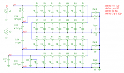
Now I have simulated a slightly different ladder, consisting of 28 resistors of 100 Ohm and 1/8W (1/4" long). They are divided in four groups, each having their own guard plane of 13*21mm (around and directly underneath the R's).
I estimated the capacitance between that plane and each resistor to 5pF and the capacitance between the guard and the ground plane beneath it to 30pF (using a four layer PCB).
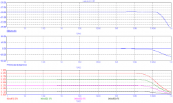
Leaving the guard plane floating, I got a phase shift of 11 degrees at 1MHz.
Bootstrapping the guard planes by means of a capacitive ladder, such that the successive voltages are 7/8, 5/8, 3/8 and 1/8 of the input voltage, extends the bandwidth to over 100MHz (see next post). More than enough for audio applications, don't you think so?
Notice R5, which prevents peaking above 100MHz.
BTW, as told in a previous post, the internal capacitance as well as the "intra capacitance" have far less impact. So I've omitted these caps in this simulation
Cheers,
Edmond.
1audio said:As you can see its about technique and tricks. I would first look at flying the array 2 CM above the board to reduce the capacitance. But that creates a window for EMI pickup and who knows what else.
Agreed.
Are you modeling the stray capacitance as a single cap from the center of each resistor to ground? (similar for the other parasitics?)
Yes
Have you measured or calculated the capacitance or just guessed (like I would)?
Just guessed.
How big are the resistors?
100 Ohm, 1/8W, 1/4"
Its a distributed effect so the curves won't be the usual 6 db per octave, they will increase with frequency.
Agreed.
You could make a tall sub board (30 1/2" resistors in series would be a loop 15" or 2 loops 7.5" high with a small window and less capacitance to ground, unless it gets close to the top of the case.
[snip]
Perhaps the trick would be to contain the resistors in a shield tied to the input (low Z source) and a shunt cap at the FB to ground to compensate for the shunt cap from the input. Eliminates the stray cap to ground. Can be done with a copper plane directly below the resistor array with a window around the last resistor. (I did something similar in the NuForce preamp.)
Hi Demian,
Thanks for the hint. I had almost forgotten that nice trick, a bootstrapped guard.
Now I have simulated a slightly different ladder, consisting of 28 resistors of 100 Ohm and 1/8W (1/4" long). They are divided in four groups, each having their own guard plane of 13*21mm (around and directly underneath the R's).
I estimated the capacitance between that plane and each resistor to 5pF and the capacitance between the guard and the ground plane beneath it to 30pF (using a four layer PCB).
Leaving the guard plane floating, I got a phase shift of 11 degrees at 1MHz.
Bootstrapping the guard planes by means of a capacitive ladder, such that the successive voltages are 7/8, 5/8, 3/8 and 1/8 of the input voltage, extends the bandwidth to over 100MHz (see next post). More than enough for audio applications, don't you think so?
Notice R5, which prevents peaking above 100MHz.
BTW, as told in a previous post, the internal capacitance as well as the "intra capacitance" have far less impact. So I've omitted these caps in this simulation
Cheers,
Edmond.
Attachments
Good work, if a little involved. It would be worth the effort to find the real values of the parasitics and throw that in. Moving the response errors to above 100 MHz should make them a non-issue. The next trick would be to use the layers of the PCB to make the capacitive divider. You would still need to compensate for the input capacitance of the feedback node (which will be a much more non-linear capacitance than the PCB).
Nordic said:I have been haveing a go at microcap the last two weeks or so... now starting to grasp the basics... very usefull for PCB design, but not useing funcitonality not available in LTspice etc...
--------
But my vote goes to Micro Cap out of all the spice tools I have played with recently
After your post, Nordic,
I downloaded a torrent version of Micro Cap 9.
I must say the default component library is among the best I have seen!
And this is a very good thing.
No simulation software is better than its library of Spice Models.
For example all EXICON Lateral MOSFET
And for JFETs like 2SK170 .... they have spice for all IDSS classes by default 😎Memo:N-ch Lateral MOS 200v 8A metal can
.MODEL ECF10N20 NMOS (LEVEL=1 CGDO=100P CGSO=100P GAMMA=0 GDSNOI=0 IS=10F
+ JS=10N KAPPA=200M KP=20U L=2U LAMBDA=3.44617M NLEV=0 NSUB=0 PHI=600M
+ RD=244.181M RDS=16.0012K RG=367.902 RS=178.517M TOX=0 TPG=1 UO=600
+ VTO=-66.415M W=76.3794M)
---- 2SK170V, 2SK170BL, 2SK170GR, 2SK170Y
search with google:
microcap v9 isohunt library
just curious....... the link has microcap pro...... is that commercial software, shareware, or what?
MicroCAP PRO is a commercial software!
Sigurd
Sigurd
unclejed613 said:just curious....... the link has microcap pro...... is that commercial software, shareware, or what?
lineup said:...................
No simulation software is better than its library of Spice Models
For example all EXICON Lateral MOSFET
...................
Level 1 MOSFET models, as in this case, are almost useless for distortion analysis. For more info on this topic read:
http://www.diyaudio.com/forums/showthread.php?postid=1295739#post1295739
Re: Nordic
Thanks burbeck, will look at it shortly, I had some PC problems that made my normal harddrive almost unusable... I foud a little app call hard disk regenerator or something like that... slow as hell but it actualy REPAIRS broken sectors as oposed to moveing data around it...
Does it work? Well I'm back...
burbeck said:hi Nordic,
here is something to get you started
component numbering different.
few errors in your circuit
some in mine im sure, but basics are ok
have fun
Thanks burbeck, will look at it shortly, I had some PC problems that made my normal harddrive almost unusable... I foud a little app call hard disk regenerator or something like that... slow as hell but it actualy REPAIRS broken sectors as oposed to moveing data around it...
Does it work? Well I'm back...
Edmond, you and your associates have proved my initial assertion that SPICE simulation without accurate models of exactly what you are using can be very misleading. That is of course why this thread was split off to address SPICE problems exclusively.
I, personally, cannot at this time, spend man-weeks making accurate models. I just build the real thing, and then adjust it to optimize it. I realize that many here have access to a good computer and lots of time, compared to having a measurement lab and willing offshore people to build prototypes, so you will spend more time with SPICE, and I will spend more time with real prototypes. Both approaches have advantages and disadvantages, but I will probably never be one of the SPICE advocates that many here are, but if I was 30-40 years younger, I might think myself in 'hog-heaven' to have access to a quality SPICE program. I had to do it with a sliderule or calculator and a piece of graph paper.
I, personally, cannot at this time, spend man-weeks making accurate models. I just build the real thing, and then adjust it to optimize it. I realize that many here have access to a good computer and lots of time, compared to having a measurement lab and willing offshore people to build prototypes, so you will spend more time with SPICE, and I will spend more time with real prototypes. Both approaches have advantages and disadvantages, but I will probably never be one of the SPICE advocates that many here are, but if I was 30-40 years younger, I might think myself in 'hog-heaven' to have access to a quality SPICE program. I had to do it with a sliderule or calculator and a piece of graph paper.
Edmond Stuart said:
Level 1 MOSFET models, as in this case, are almost useless for distortion analysis. For more info on this topic read:
http://www.diyaudio.com/forums/showthread.php?postid=1295739#post1295739
Yes, I am aware of this.
And just because a spice file is called xxxxxx.sp3
it may very well have a level 1 model and not LEVEL 3
So, Edmond
you use only LEVEL 3 models?
I guess not ....
Hi John,
Indeed, we use different approaches. These are not only based on our preferences, but also on our circumstances. You have many lab resources and I have (after my retirement) plenty of time and far less lab equipment (only the basic stuff like scopes, signal generators and a distortion analyzer). But that's not all: I really hate designing PCBs, not to mention possible wiring or design errors. Therefore, in an attempt to avoid a (costly) PCB redesign, I'm using a simulator to detect possible errors in an early stage.
This approach will not always shorten the design cycle. As for my latest design (PCP amp), it takes a lot of time, by now, six month. Apart from convergence errors, the problem with this complex design is that, after each modification, one has to check not only things like distortion, bias current, PSRR, overload recovery, etc., but also all possible sources of instability: Miller loops, (global) NFB loops, CMCL's etc. (including loops in the regulated PSUs!)
In this regard I've learned from the PGP project: An early version started oscillating when the output exceeded a certain level (20V or so). The simulator did not reveal this. But if I had looked a bit closer, I should have discovered that indeed something was wrong: the phase margin of the Miller loop (around the VAS) was dangerous low, only 20 deg.
Anyhow, one thing is for sure: in the final end one has to build the thing in order to put in the final tweaks (and listen!)
Cheers,
Edmond.
- Home
- Design & Build
- Software Tools
- Spice simulation