lineup said:
Yes, I am aware of this.
And just because a spice file is called xxxxxx.sp3
it may very well have a level 1 model and not LEVEL 3
So, Edmond
you use only LEVEL 3 models?
I guess not ....
the SP3 file is a SPICE 3 file, not neccesarily a LEVEL 3 model. however, since SPICE models are usually text files, most manufacturer models state what LEVEL model they are in a comments section. not all of them do.
lineup said:.............
So, Edmond
you use only LEVEL 3 models?
I guess not ....
As for MOSFETs I'm using BSIM-V3.3 (level=8) or EKV models (level=44)
Cheers,
Edmond.
Edmond Stuart said:Hi John,
Indeed, we use different approaches. These are not only based on our preferences, but also on our circumstances. You have many lab resources and I have (after my retirement) plenty of time and far less lab equipment (only the basic stuff like scopes, signal generators and a distortion analyzer). But that's not all: I really hate designing PCBs, not to mention possible wiring or design errors. Therefore, in an attempt to avoid a (costly) PCB redesign, I'm using a simulator to detect possible errors in an early stage.
This approach will not always shorten the design cycle. As for my latest design (PCP amp), it takes a lot of time, by now, six month. Apart from convergence errors, the problem with this complex design is that, after each modification, one has to check not only things like distortion, bias current, PSRR, overload recovery, etc., but also all possible sources of instability: Miller loops, (global) NFB loops, CMCL's etc. (including loops in the regulated PSUs!)
In this regard I've learned from the PGP project: An early version started oscillating when the output exceeded a certain level (20V or so). The simulator did not reveal this. But if I had looked a bit closer, I should have discovered that indeed something was wrong: the phase margin of the Miller loop (around the VAS) was dangerous low, only 20 deg.
Anyhow, one thing is for sure: in the final end one has to build the thing in order to put in the final tweaks (and listen!)
Cheers,
Edmond.
Edmond,
All so very true.
WRT your PCP amp, can you tell us what are the design goals?
cheers
Terry
PCP
Hi Terry,
The design goals are similar to those for the PGP amp, 200W into 4Ohm and THD20 < 1ppm. However, the architecture is quite different. NFB instead of EC applied to the output stage, TTMC instead of NDFL and four pair of vertical MOSFETs instead of three lateral pairs as output devices. Also auto-bias and over-current protection. It comprises about 70! trannies, hence its name: Pretty Complex Power amp.
For some precursors, see my website: http://home.tiscali.nl/data.odyssey/PMP.html
Cheers,
Edmond.
Terry Demol said:Edmond,
All so very true.
WRT your PCP amp, can you tell us what are the design goals?
cheers
Terry
Hi Terry,
The design goals are similar to those for the PGP amp, 200W into 4Ohm and THD20 < 1ppm. However, the architecture is quite different. NFB instead of EC applied to the output stage, TTMC instead of NDFL and four pair of vertical MOSFETs instead of three lateral pairs as output devices. Also auto-bias and over-current protection. It comprises about 70! trannies, hence its name: Pretty Complex Power amp.
For some precursors, see my website: http://home.tiscali.nl/data.odyssey/PMP.html
Cheers,
Edmond.
Re: PCP
Hi Edmond,
I look forward to seeing it, I am sure there will be some surprises
for us. Your last project was astounding.
It appears pcp will be more comfortable with difficult loads.
OK, apologies for slight subject shift - back to spice.
Cheers
Terry
Edmond Stuart said:
Hi Terry,
The design goals are similar to those for the PGP amp, 200W into 4Ohm and THD20 < 1ppm. However, the architecture is quite different. NFB instead of EC applied to the output stage, TTMC instead of NDFL and four pair of vertical MOSFETs instead of three lateral pairs as output devices. Also auto-bias and over-current protection. It comprises about 70! trannies, hence its name: Pretty Complex Power amp.
For some precursors, see my website: http://home.tiscali.nl/data.odyssey/PMP.html
Cheers,
Edmond.
Hi Edmond,
I look forward to seeing it, I am sure there will be some surprises
for us. Your last project was astounding.
It appears pcp will be more comfortable with difficult loads.
OK, apologies for slight subject shift - back to spice.
Cheers
Terry
Re: Re: PCP
[OT]

 😡
😡
[/OT]
Terry Demol said:
Hi Edmond,
Your last project was astounding.
[OT]
😡 [/OT]
Edmond Stuart said:
As for MOSFETs I'm using BSIM-V3.3 (level=8) or EKV models (level=44)
Cheers,
Edmond.
Edmond and Andy_c,
I've also done some poking around with actual vertical power MOSFET measurements at low drain currents (10 mA to 1.5A) and found that the Level 1 SPICE models do not reflect the Id vs Vgs performance well in this region. And it does indeed seem true that the wingspan simulation of a Class AB MOSFET output stage is much worse as a result of the simple square law model in SPICE. Same for THD level and spectra.
Transconductance as a function of drain current for the square law model is just way off the mark. The exponential behavior of Id vs Vgs in the low-current region, and the transition to the square-law behavior, needs to be properly modeled, else one gets pessimistic distortion simulations. Waht did surprize me was that the area of inaccuracy of the simple SPICE model seems to be in a current region for vertical MOSFETs that is well above what we would normally think of as the threshold voltage. In other words, this "sub-threshold" behavior and region seems to extend further above threshold than I would have thought. Significant modeling error of Id vs Vgs and gm vs Ids seems to exist in the region of Id extending to a couple hundred mA. Have you guys noticed this?
It seems to me it would be REALLY nice if the LTspice VDMOS model supported the BSIM3 model for its DC part. I don't believe it does, however.
I don't think I've had too much luck with the EKV models in LTspice, but the BSIM3 may work better. Do either of you guys have a procedure for making up a BSIM3 model given measured Id vs Vgs data. What has your experience been in this regard? My familiarity with BSIM3 models is limited. All I really care about at this point is getting a much better fit of Id vs Vgs to the real-world behavior of real vertical MOSFETs.
Cheers,
Bob
Hi Bob,
I don't have a BSIM extraction procedure.
You might try out the EKV models for the IRFP244 and FQA9P25. I've been using them for a while without trouble. I fixed these up after I found the problem that caused convergence errors in the Toshiba models. I haven't gone back and fixed the Toshiba MOSFET models.
These IRF and Fairchild models can be found starting here.
andy_c said:Hi Bob,
I don't have a BSIM extraction procedure.
You might try out the EKV models for the IRFP244 and FQA9P25. I've been using them for a while without trouble. I fixed these up after I found the problem that caused convergence errors in the Toshiba models. I haven't gone back and fixed the Toshiba MOSFET models.
These IRF and Fairchild models can be found starting here.
Thanks, I'll give it a shot.
Bob
I have used these models in the past with LTspice and they seemed to work: Supertex They didn't crash or fail to converge and the biases were pretty close to the real parts in a PCB. I'm not sure just how precise they are. however this class of devices are rarely used for linear applications so the precision of the transfer curve is secondary to the modeling of the charges when switching the device on and off, at least for their target customers.
1audio said:I have used these models in the past with LTspice and they seemed to work: Supertex They didn't crash or fail to converge
and the biases were pretty close to the real parts in a PCB.
.. were pretty close to the real parts in a PCB.
Just another testimony in a long row of verdicts from experienced Spice users.
That spice works. And works Pretty Well.
We have had the same opinion from Robert Cordell.
And Mr Cordell is certainly not a man that is way off of reality.
Like any map or model of reality, there are differences.
These difference can however be so small that it is not of crusial importance.
Take watching TV or listen to a music recording.
🙂 1. Your TV picture is NOT reality. It is model, an image of a real environment.
It shows you something like what is at a certain place.
It does far from show you everything.
The soundtrack will not give you all sounds.
There are no smells.
The colours are not in 100% tone with real place.
Still you accept your TV-set's image of reality.
Because, in many cases, it gives you a fair perception of the real thing.
🙂 2. Your music listening.
Behold that you are actually not listening to the real original sounds.
It is an re-produced virtual version of sounds from another time and place.
Or it is just virtual synthetically produced sounds from a mixer studio.
The data used to TRY TO recreate the original soundtrack
is a description stored in a media.
Might be data from an analog media, like magnetic fields in a tape, or grooves in a plastic material.
Or may be digital data samples stored in a digital media.
What is different is not only the reproduced sound waves.
It is very much also YOUR ROOM.
It is probably very far from alike where microphones tried to do a good job.
--------
If now, we accept using models or images of reality in some cases,
I can not understand why not accept or respect the use of it in The Spice case.
We have never said that Spice is the real thing.
We know it is not reality.
But we will never tell you anything else but that
Spice is a very good tool & can help us to understand real circuit.
😎 Very much so!
Lineup, Sweden July 2008
HI!
I did some search with google. I got 2 spice model. I don't know which model is right.
.model 2SC3281_1 NPN (IS=10F BF=107.06 VAF=100 IKF=16.941 ISE=0.578669F NE=1.14481 BR=10 IKR=1.04175 ISC=1.21848E-05F NC=2.99843 RE=1 RC=30.7022M CJE=600P MJE=350M CJC=1.05579N VJC=700M MJC=500.059M TF=4.16856N XTF=500M VTF=10 ITF=10.4762M TR=10N RB=0.16 XTB=2.0 Vceo=200 Icrating=15000m)
.model 2SA1302_1 PNP (IS=10F BF=129.738 VAF=100 IKF=16 ISE=0.414467F NE=1.12865 BR=10 IKR=9.99995 ISC=2.16381N NC=2.21849 RE=1 RC=149.165M CJE=800P MJE=350M CJC=1.83549N VJC=699.998M MJC=499.587M TF=6.72889N XTF=444.956M VTF=10.5982 ITF=1.13444P TR=10N RB=0.22 XTB=1.2
Vceo=200 Icrating=15000m)
.MODEL 2SC3281_2 NPN( IS=10.000E-15 BF=155.65 VAF=100 IKF=9.2028 XTB=1.5 ISE=54.325E-15 NE=1.3056 BR=10.787 VAR=100 IKR=1.8561 ISC=106.69E-15 NC=1.6728 NK=.55624 RC=26.745E-3 CJE=2.0000E-12 CJC=534.41E-12 MJC=.33333 TF=8.0821E-9 XTF=3.1968 VTF=21.461E-3 ITF=169.59 TR=187.91E-9)
.MODEL 2SA1302_2 PNP( IS=21.479E-12 BF=136.48 VAF=100 IKF=19.980 ISE=21.504E-12 NE=1.3784 BR=329.48 VAR=100 IKR=19.980 ISC=4.3670E-9 NC=1.4264 NK=.72845 RC=93.301E-3 CJE=755.31E-12 MJE=.33333 CJC=1.1417E-9 MJC=.33333 TF=1.2802E-9 XTF=10 VTF=10 ITF=1 TR=10.000E-9)
thanh said:I did some search with google. I got 2 spice model. I don't know which model is right.
.model 2SC3281_1 NPN
.model 2SA1302_1 PNP
.MODEL 2SC3281_2 NPN
.MODEL 2SA1302_2 PNP
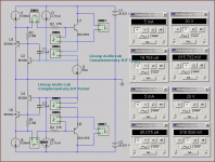
Setup a complementary BJT tester in your Sim.
I have such a circuit saved, that use.
This way I can see if there is something Not Normal .. for example with VBE.
My circuit works at higher Ampere: 1 - 2 A
But also at very low currents.
As you can see, the same current goes into NPN as into PNP.
You just have to change 1 Current source.
Attachments
thanks lineup!
I just simulated my amp with these models. A model gived a good result and another is otherwise. Perhaps a bad/wrong model can be good😀
I just simulated my amp with these models. A model gived a good result and another is otherwise. Perhaps a bad/wrong model can be good😀
Bob Cordell said:Edmond and Andy_c,
I've also done some poking around with actual vertical power MOSFET measurements at low drain currents (10 mA to 1.5A) and found that the Level 1 SPICE models do not reflect the Id vs Vgs performance well in this region. And it does indeed seem true that the wingspan simulation of a Class AB MOSFET output stage is much worse as a result of the simple square law model in SPICE. Same for THD level and spectra.

Transconductance as a function of drain current for the square law model is just way off the mark. The exponential behavior of Id vs Vgs in the low-current region, and the transition to the square-law behavior, needs to be properly modeled, else one gets pessimistic distortion simulations. What did surprise me was that the area of inaccuracy of the simple SPICE model seems to be in a current region for vertical MOSFETs that is well above what we would normally think of as the threshold voltage. In other words, this "sub-threshold" behavior and region seems to extend further above threshold than I would have thought. Significant modeling error of Id vs Vgs and gm vs Ids seems to exist in the region of Id extending to a couple hundred mA. Have you guys noticed this?
Hi Bob,
Yes, I did have noticed that too, up to ~300mA.
It seems to me it would be REALLY nice if the LTspice VDMOS model supported the BSIM3 model for its DC part. I don't believe it does, however.
I don't think I've had too much luck with the EKV models in LTspice, but the BSIM3 may work better. Do either of you guys have a procedure for making up a BSIM3 model given measured Id vs Vgs data. What has your experience been in this regard? My familiarity with BSIM3 models is limited. All I really care about at this point is getting a much better fit of Id vs Vgs to the real-world behavior of real vertical MOSFETs.
Cheers,
Bob
Regrettably I can't offer you a automated procedure for capturing the BSIM3 parameters. I did a least square fit 'by eye' of Id vs Vgs, that is, by simultaneously plotting the (interpolated) 'ist' and 'soll' curves and endless fiddling with a limited set of parameters (about 8) until both curves reasonably coincided.
To get the capacitances right, I had to add diodes (copied from other models) and adjusted some parameters so that they were in accordance with the values of the data sheet within ~10%.
All in all, not very 'scientific', but for the purpose (i.e. estimation of the distortion) I think it's sufficient.
Cheers,
Edmond.
thanh said:thanks lineup!
I just simulated my amp with these models. A model gived a good result and another is otherwise. Perhaps a bad/wrong model can be good😀
I'm sorry! I just simulated my amp with these models. A model gived a good result and another is otherwise. Perhaps a bad/wrong model can not be good😀
Interesting question.
If one model is not correct/bad = does not show close to the curves of the transistor,
can one amplifier using this model/transistor be good/better in Simulation?
We have to say YES.
Because if the model is not correct,
it can be 'too good model'. Better than Reality.
Or 'too bad data' for this transistor.
The only thing we can do is to try to verify a model, if not sure it is close to real.
And there are only 2 good ways to do this:
1. Check against real measured data/curves taken from a REAL Transistor.
2. Check against some data/curves, that some other person has measured.
Most often those curves in DATASHEET.
Edmond Stuart said:
Hi Bob,
Yes, I did have noticed that too, up to ~300mA.
Regrettably I can't offer you a automated procedure for capturing the BSIM3 parameters. I did a least square fit 'by eye' of Id vs Vgs, that is, by simultaneously plotting the (interpolated) 'ist' and 'soll' curves and endless fiddling with a limited set of parameters (about 8) until both curves reasonably coincided.
To get the capacitances right, I had to add diodes (copied from other models) and adjusted some parameters so that they were in accordance with the values of the data sheet within ~10%.
All in all, not very 'scientific', but for the purpose (i.e. estimation of the distortion) I think it's sufficient.
Cheers,
Edmond.
Edmond,
Thanks for your comments. It did appear that the EKV models referred to by Andy_c above gave a pretty good fit to the Id vs Vgs curves for the IRFP244, and gave a well-behaved wingspan plot. It is unfortunate that the manufacturer-supplied curves often go down only to about Id = 100 mA, and are difficult to accurately read at that point. I have resorted to measuring my own real IRFP240 and IRFP9240 devices down to about 10 mA, but don't have a good feel for manipulating the BSIM3 parameters to get a good fit.
Cheers,
Bob
Bob Cordell said:Edmond,
[snip]
It is unfortunate that the manufacturer-supplied curves often go down only to about Id = 100 mA, and are difficult to accurately read at that point.
[snip]
Cheers,
Bob
Hi Bob,
The only company, AFAIK, that publishes sub-threshold data (down to 1uA) is NXP (formerly Philips), see attached example.
Cheers,
Edmond.
Attachments
- Home
- Design & Build
- Software Tools
- Spice simulation