Just wondering when you test your static parameters from post #389, do you let the rest of the parameters go to the SPICE defaults?
Pete B.
Pete B.
No, to what are called "typical values".
The problem I'experiencing now with the 13050 is that it seems that the formula
IC=IS*exp(Vbe/NF*Vt)
that should be valid for small values of Vbe gives unreliable values. It seems that a precise value of VAF (and of VAR ?) is needed, but it seems that there is no way to find it independently.
A solution where ALL the parameters enter in the optimization process can be found, but the values for those parameters are quite fancy (and, I guess, not physical).
A question: how the curves of V(BE)sat and V(CE)sat are analytically described by the G-P model ? The PSPICE Modeler uses them also, but I don't know how.
teodorom said:No, to what are called "typical values".
Sorry, not following your "typical values" are you referring to the SPICE defaults that I had asked about?
Pete B.
This is the link to the Agilent paper (the most detailed paper found so far on that subject): http://eesof.tm.agilent.com/docs/iccap2002/MDLGBOOK/7DEVICE_MODELING/3TRANSISTORS/1GummelPoon/GP_DOCU.pdf
Yes, I saw that paper but have only skimmed it so far.
Let me pose another related question.
The max Ib for these parts is 1.5 A, and I'm seeing a Vbe of about 6V for Andy's model, and about 9 V for your model at Ib = 1.5 A.
This is obviously mostly a result of the Rb value.
Has anyone tested these parts, and do they have a deliberate built in high Rb perhaps as a built in base stopper, or do we need to use IRB, and RBM to get more reasonable results?
Figure 6. in the OnSemi data sheet for the NPN MJL3281a shows for Ic/Ib=10, that at Ic=20A the typical Vbe is about 1.8V with a Vce of 1V. So, it seems that we do need to determine values for IRB and RBM to provide a closer match.
I'm interested in this because the simulation results are not so good for a power amp that I'm simulating under output short circuit fault conditions. It's a minor point, the models otherwise seem to work very well.
Thoughts?
Pete B.
andy_c said:
Hi Scott,
Are you talking HSPICE here? I'm looking in Massobrio and Antognetti, and the only quasi-sat parameter documentation in there is HSPICE-specific (level=2). AFAIK, LTspice doesn't have them. At least, I don't see any parameters in the LTspice SGP documentation that aren't in the SGP parameter descriptions in Massobrio and Antognetti.
I only mentioned quasi-sat because of Teodoro's post and graph here. That kind of behavior (negligible change in beta at low currents as Vcb is changed, but much larger changes in beta as Vcb is changed at high current) imply something akin to a lower Early voltage at higher Ic. You can also see this effect in the Ic vs. Vbe curves at two different Vcb values (see below).
Edit: Also, what I'm reading from some internet references is that quasi-sat also accounts for the sharp dropoff in fT at high currents - something I can't get the SGP models to handle correctly for the OnSemi power devices.
Hi andy,
I was actually talking our own in house SPICE and it does model ft drop and dynamic base charge (a large effect). Reality and simulation match to a scary degree. I also know we export encripted HSPICE decks based on Mextram? models to large customers.
PB2 said:
... The value was completely off, being 2 ohms in the OnSemi model.
Pete B.
A typo, that should have been .2 ohms based on what Andy reports in his analysis. Still high.
I notice that OnSemi revised their models on May 3, 07 with a new RC value of .051212 for the MJL3281a. Does anyone know if these are good models?
I also notice that this model includes:
RB=1.0642 IRB=2.65716 RBM=1.0642
Note that RB = RBM which is the same as omitting IRB and RBM, also note the low value of about 1 ohm.
Pete B.
Rb, Irb, Rbm
I've been digging into this more, reading several of the references and Andy's web page. I didn't find Andy's Figure 1 in the OnSemi data sheet for the MJL3281, but did find it in the data sheet for the NJL3281 which is the same die as I understand it.
Andy makes it clear that he does not model the Quasi Saturation region, and we have to keep in mind that these are fairly high beta devices in the active region. Beta is usually 50 to 100 for Ic < 10 A and Vce's of 5V or more. This means that Ib is usually below, often well below 200 mA in the active region.
The data in OnSemi's Figure 6 (for the NJL3281) can be used to extend the hFE versus Ic curve and to determine Ib for Ic values up to 25 A for the Vbe vs. Ic curves in Figure 10. This provides Vbe vs. Ib data for higher Ib values that can be used to test/improve the various models.
Using the NJL3281 data for Vce=5V I get:
Ic=20 A, Ib = .6 A, Vce = 2.4 V
Ic=25 A, Ib = 1 A, Vce = 3.0 V
with rough extrapolation:
Ic=30 A, Ib = 2A, Vce = 4.0 V
Comparing these numbers to the new Onsemi model shows that it predicts a very low Vbe of 1.47, 1.91, and 3.0V for Ib = .6, 1, and 2 A. Andy's model is high but it was not his intent to model beyond the linear region. The values for Vbe are: 3.18, 4.80, and 8.80 Vbe for the respective Ib currents.
I'm thinking that Andy's curve fit for Vbe vs. Ib is very good up to about Ib=100 or 200 mA, which was his goal for modelling the active region.
I'm experimenting with IRB and RBM to improve the fit at higher currents.
Pete B.
njl3281 model from OnSemi
Just noticed that the njl3281d model from OnSemi is not the same as the mjl3281; it is also a May 07 model:
RB=5.68023, IRB=0.1, RBM=0.253
Will test it when I have some free time.
Pete B.
Just noticed that the njl3281d model from OnSemi is not the same as the mjl3281; it is also a May 07 model:
RB=5.68023, IRB=0.1, RBM=0.253
Will test it when I have some free time.
Pete B.
I guess that there is little hope in finding the appropriate SGP parameters from the datasheets.
The best (that is more predictable) approach I was able to find followed these steps:
The best (that is more predictable) approach I was able to find followed these steps:
- get IS and NF starting from IC(VBE) for little values of VBE (that is in situations where the effects of RB are negligible)
- get BF, ISE, NE, IKF by optimization (using FindMinimum of Mathematica or Minerr with the Levengberg-Marquandt method of Mathcad): however I needed to accept the value of VAF proposed by the manifacturer, since there is no way to find it from the datasheets
- get RB from the fit of VBE(IB)+RB*RB with the values of the (external) VBE
[/list=1]
I tried a "global" approach, that is I used NMinimize of Mathematica, but with unreliable results. The best thing is to use methods that start from a "guess" value.
However this "guess" value is a lot critical and I have not yet found a way to find some a good value for it.
Sometimes I get better results with Mathcad than with Mathematica.
The remaining parameters are really impossible to find.
New 2SC3601/2SA1407 models
I have posted here http://www.diyaudio.com/forums/showthread.php?postid=1345609#post1345609 the 2SC3601/2SA1407 models that we used to design the PGP.
Find attached new models for the same pair; they are supposed to be much better, as they fit pretty well the devices datasheet curves. The models are for PSpice, I suppose porting to other platforms should not be a big deal.
Attachments
Re: New 2SC3601/2SA1407 models
Thanks, Ovidiu,
I have been using some fixed-up models of these devices as well, but all I did was fix Is and RE. The original models were way off in the IC-Vbe characteristic. I'm sure you've done a more thorough job than I did. I'll take a look and compare. Thanks again.
Bob
syn08 said:I have posted here http://www.diyaudio.com/forums/showthread.php?postid=1345609#post1345609 the 2SC3601/2SA1407 models that we used to design the PGP.
Find attached new models for the same pair; they are supposed to be much better, as they fit pretty well the devices datasheet curves. The models are for PSpice, I suppose porting to other platforms should not be a big deal.
Thanks, Ovidiu,
I have been using some fixed-up models of these devices as well, but all I did was fix Is and RE. The original models were way off in the IC-Vbe characteristic. I'm sure you've done a more thorough job than I did. I'll take a look and compare. Thanks again.
Bob
teodorom said:I guess that there is little hope in finding the appropriate SGP parameters from the datasheets.
The best (that is more predictable) approach I was able to find followed these steps:
- get IS and NF starting from IC(VBE) for little values of VBE (that is in situations where the effects of RB are negligible)
- get BF, ISE, NE, IKF by optimization (using FindMinimum of Mathematica or Minerr with the Levengberg-Marquandt method of Mathcad): however I needed to accept the value of VAF proposed by the manifacturer, since there is no way to find it from the datasheets
- get RB from the fit of VBE(IB)+RB*RB with the values of the (external) VBE
[/list=1]
I tried a "global" approach, that is I used NMinimize of Mathematica, but with unreliable results. The best thing is to use methods that start from a "guess" value.
However this "guess" value is a lot critical and I have not yet found a way to find some a good value for it.
Sometimes I get better results with Mathcad than with Mathematica.
The remaining parameters are really impossible to find.
Yes, I see your point, however it seems to me based on my previous posts that there is enough data to get a least a few points up around Ib=.5 to 1A and getting a better fit in this region would be good enough for my purposes. It seems to me that there is also enough data to determine beta at these Vce and current levels to provide a few more points for a curve fit.
I do think it would be helpful to "seed" the optimizer with a decent starting point, but this is a complex problem and I just don't have the time to work on it in the near term.
I don't think you've posted your full procedure so it is difficult to comment. Andy's procedure looks quite good based on what I read of it and his goals.
Something else to keep in mind is that there is usually a fairly large spread in the semiconductor process so the question arises should SPICE models provide a worst case performance, or closer to the center of the performance curve.
Pete B.
I have uploaded some PDF of my worksheets.
http://teodorom.atspace.com/Temp/Static Parameters.MJL1302A.pdf
http://teodorom.atspace.com/Temp/Static%20Parameters.GOOD.hFE(IC).3281A.pdf
http://teodorom.atspace.com/Temp/Static%20Parameters.MJE15031.pdf
http://teodorom.atspace.com/Temp/Static%20Parameters.MJE15030.pdf
There are examples where as imput data I have used correlated triples (Ic, VBE, hFE and the Ib), or uncorrelated couples (hFE vs/ Ic), (VBE vs/ Ic). It seems that the amount of input data is not important.
Hi, Everybody,
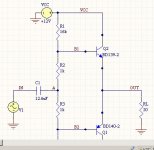
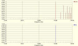
I'm learning simulation. I try to simulate this simple pushpull cct. The signal generator is 10khz, 1V. The FFT is with 10khz fundamental frequency.
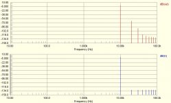
I got very different FFT result with BD139-BFD140 model from 2 manufacturers (with exactly the same CCT). Which is the right one?
This is the CCT being simmed.
I'm learning simulation. I try to simulate this simple pushpull cct. The signal generator is 10khz, 1V. The FFT is with 10khz fundamental frequency.
I got very different FFT result with BD139-BFD140 model from 2 manufacturers (with exactly the same CCT). Which is the right one?
This is the CCT being simmed.
Attachments
Hi,
the predictions are only as good as the models (data) input into the equations.
Different models will give different results.
Wrong models will give useless results.
Trying to get distortion results from these simulators is stretching the manufacturers' standard models to or beyond their limits.
That's why the experienced among us say design, build, test.
AndrewT said:
Wrong models will give useless results.
Trying to get distortion results from these simulators is stretching the manufacturers' standard models to or beyond their limits.
That's why the experienced among us say design, build, test.
Not really true. Some models have problems, but you don't end up with useless results. There have been many warnings about the ONsemi models (BD139/140 among them).
Simulation gives distortion figures that are very close to the real thing. In fact, I find the simulation errs on the side of caution, and the real circuit may well have lower distortion than predicted.
For example: my predicted distortion for this amp (Andrew, you were involved) was <.010%. The results were better than that.
Nice to design on paper, but using a simulation would be the next logical step, certainly before building it.
AndrewT said:Wrong models will give useless results.
only if the models are good.MJL21193 said:Simulation gives distortion figures that are very close to the real thing.
If the results are unreliable then that is the same as useless.
- Home
- Design & Build
- Software Tools
- Spice simulation