teodorom said:I have just developed (with Mathematica) a procedure able to extract (without any explicit, manual, recursion) those static, forward, parameters. For the others I assume the "typical" value.
The great uncertainty is the value of VAF: many times there is no way to get it.
Nice work - congratulations!
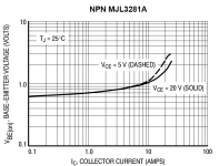
Regarding the VAF value and the OnSemi power devices - that is a tough one. Looking at the Ic vs Vbe curves for the two different Vce values, the curves seem to fall on top of each other at low and mid currents. This implies a nearly infinite Early voltage. But they separate quite a bit at high currents, implying some kind of reduction of Early voltage at high current. If you choose VAF to get the correct separation at high currents, the simulated separation at low currents is a lot more than what the datasheet shows. This seems to imply the the Gummel-Poon Early voltage model is not adequate. I have heard that VBIC uses a bias-dependent Early effect model for quasi-saturation, so maybe that's a known problem with Gummel-Poon.
I've got reasonable results for MJL1302A, MJL3281A, MJL4302A, MJL4281A. With the MJE15030 I had some problems (BF too high, when compared to hFE, convergence problems).
More over I have problems with the displacement of the "beta droop" when varying VCE (I guess it is a problem of the SGP model).
Thanks
I'm not sure the high BF is a problem. If the non-ideal Ib and Ic vs. Vbe regions overlap such that there is no region where beta is constant, BF can end up being a lot higher than the actual maximum beta. I suspect the additional falloff in beta at low Vce and high Ic in the measured data would need a bias-dependent Early effect to describe, so I think this is indeed a weakness in Gummel-Poon as you say.
andy_c said:
Nice work - congratulations!
Regarding the VAF value and the OnSemi power devices - that is a tough one. Looking at the Ic vs Vbe curves for the two different Vce values, the curves seem to fall on top of each other at low and mid currents. This implies a nearly infinite Early voltage. But they separate quite a bit at high currents, implying some kind of reduction of Early voltage at high current. If you choose VAF to get the correct separation at high currents, the simulated separation at low currents is a lot more than what the datasheet shows. This seems to imply the the Gummel-Poon Early voltage model is not adequate. I have heard that VBIC uses a bias-dependent Early effect model for quasi-saturation, so maybe that's a known problem with Gummel-Poon.
I'm not sure the high BF is a problem. If the non-ideal Ib and Ic vs. Vbe regions overlap such that there is no region where beta is constant, BF can end up being a lot higher than the actual maximum beta. I suspect the additional falloff in beta at low Vce and high Ic in the measured data would need a bias-dependent Early effect to describe, so I think this is indeed a weakness in Gummel-Poon as you say.
There's an extended Gummel-Poon model that handles quasi-sat. AFAIK the standard model does not handle it at all.
BTW Andy,
Is quasi-sat that big a deal in high power devices? I can see pushing the Bvceo up makes you do the wrong thing with the collectors, vis a vis quasi-sat, but I would have thought the process guys would have fixed that considering they're making only one flavor of device at a time.
Funny thing I got burnt by quasi-sat almost as I was typing the above note (it's a real problem in high (well relatively) voltage and speed IC prosesses.
I have some 10-20min simulations running which gives me a little chat time in-between.🙂 Make note to self: rearrange office so back is not to door or get diyaudio to look like MS Outlook.
Re: Re: Re: Re: Tweaking SPICE Models
Thanks, Scott. I'll try a little bit of tweaking this weekend.
My office is already optimally arranged for occasional diyaudio distractions 🙂.
Cheers,
Bob
scott wurcer said:
You're on the right track. You want to get the collector current vs. Vbe right first. rbb and RC and beta are second order, but keep in mind beta and Early voltage tend to be a constant product and a very low early voltage can complicate things a little (start at low Vcb for your first shot). I do rbb by measuring noise on a small signal transistor. Those 10-20 Ohm values are off for all but really low noise small signal transistors. Power devices OTOH have very low parasitic resistances by necessity.
Thanks, Scott. I'll try a little bit of tweaking this weekend.
My office is already optimally arranged for occasional diyaudio distractions 🙂.
Cheers,
Bob
scott wurcer said:
There's an extended Gummel-Poon model that handles quasi-sat. AFAIK the standard model does not handle it at all.
Yes, most simulators provide an extended or modified Gummel-Poon model to handle high currents. OnSemi models are of this type and LTSpice that many of us use here handles them. I notice that the Fairchild and Phillips models that I mentioned earlier are straight Gummel-Poon, not modified. The Irb and Rbm parameters alter the Rb behavior at high currents.
Pete B.
Irb, Rbm
I noticed that the 1220 and 2690 models provided here include the Irb and Rbm parameters:
http://www.diyaudio.com/forums/showthread.php?postid=1346216#post1346216
Anyone notice a problem with them when comparing the 1220 to the 2690?
Pete B.
I noticed that the 1220 and 2690 models provided here include the Irb and Rbm parameters:
http://www.diyaudio.com/forums/showthread.php?postid=1346216#post1346216
Anyone notice a problem with them when comparing the 1220 to the 2690?
Pete B.
Repeating some of the parameters in question:
Q2SA1220A PNP
+ RB =2.26
+ RBM =0.2308
+ IRB =0.001
Q2SC2690A NPN
+ RB =2.98
+ RBM =0.001
+ IRB =0.6396
Q2SA1220A PNP
+ RB =2.26
+ RBM =0.2308
+ IRB =0.001
Q2SC2690A NPN
+ RB =2.98
+ RBM =0.001
+ IRB =0.6396
scott wurcer said:There's an extended Gummel-Poon model that handles quasi-sat. AFAIK the standard model does not handle it at all.
Hi Scott,
Are you talking HSPICE here? I'm looking in Massobrio and Antognetti, and the only quasi-sat parameter documentation in there is HSPICE-specific (level=2). AFAIK, LTspice doesn't have them. At least, I don't see any parameters in the LTspice SGP documentation that aren't in the SGP parameter descriptions in Massobrio and Antognetti.
I only mentioned quasi-sat because of Teodoro's post and graph here. That kind of behavior (negligible change in beta at low currents as Vcb is changed, but much larger changes in beta as Vcb is changed at high current) imply something akin to a lower Early voltage at higher Ic. You can also see this effect in the Ic vs. Vbe curves at two different Vcb values (see below).
Edit: Also, what I'm reading from some internet references is that quasi-sat also accounts for the sharp dropoff in fT at high currents - something I can't get the SGP models to handle correctly for the OnSemi power devices.
Attachments
Okay, I found the quasi-saturation parameters in an online PSPICE manual here on page 212.
Looks like the parameters are VO, RCO, QCO and GAMMA. These aren't covered in Massobrio and Antognetti, but the reference below describes them:
"[3] G. M. Kull, L. W. Nagel, S. W. Lee, P. Lloyd, E. J. Prendergast, and H. K. Dirks, “A Unified Circuit Model for Bipolar Transistors Including Quasi-Saturation Effects,” IEEE Transactions on Electron Devices, ED-32, 1103-1113 (1985)."
In looking at Massobrio and Antognetti, the HSPICE level=2 BJT is stated as being based on this article and they say PSPICE is the same a SPICE2 - which is out of date. So it looks like PSPICE implemented it after Massobrio and Antognetti was written but HSPICE implemented it earlier. Also, I was wrong earlier about LTspice - it uses the VO, RCO, QCO and GAMMA parameters as PSPICE does.
Confusing! But maybe this can be used to improve the models.
I thought we were mostly talking about Rb, and perhaps Rc, Re.
I found this reference for the modified Gummel-Poon model which LTSpice supports:
http://www.eecg.toronto.edu/~johns/spice/part3.html
Then this for quasi-sat, which seems to be more concerned with RC being current dependent:
http://scitation.aip.org/getabs/ser...00145000002000066000001&idtype=cvips&gifs=yes
Andy, do you believe that the curve you show is an issue with quasi-sat? Or is there a mechanism for beta droop being Vce dependent? I'd think that the Vce of 5 and higher would not be in quasi-sat, but I'm not sure, I see you have a reference there for the model.
I thought I had a reference for the different SPICE BJT model levels, have to look for it again.
I got out my semiconductor device physics books, this is not good, could be a huge time sink, LOL!
Pete B.
PB2 said:I thought we were mostly talking about Rb, and perhaps Rc, Re.
Well, it looks like there are at least two conversations going on here 🙂. Sorry for the confusion.
I found this reference for the modified Gummel-Poon model which LTSpice supports:
http://www.eecg.toronto.edu/~johns/spice/part3.html
I looked at that one. It seems to cover everything that Massobrio and Antognetti cover - namely, omitting quasi-saturation.
Andy, do you believe that the curve you show is an issue with quasi-sat?
I was originally thinking that, but when I looked at the equivalent circuit for quasi-sat, it looks like its effect in the model is a base current thing (Ibs, see attached graphic). So this would not be related to the collector current plot I posted earlier. It looks like to model the Vce-dependent beta droop may require a bias-dependent Early effect as VBIC uses - but I'm not sure. Maybe it could be handled by the quasi-sat stuff. I'd have to look into it more.
Or is there a mechanism for beta droop being Vce dependent? I'd think that the Vce of 5 and higher would not be in quasi-sat, but I'm not sure, I see you have a reference there for the model.
That's a good question, and the more I look at this, the more confused I get 🙂.
I thought I had a reference for the different SPICE BJT model levels, have to look for it again.
It looks like the "level=" thing for BJT models is only used by HSPICE, not Berkeley SPICE, PSPICE, LTspice or Posh SPICE 🙂.
I got out my semiconductor device physics books, this is not good, could be a huge time sink, LOL!
Massobrio and Antognetti is usually the place to go for Gummel-Poon info, but they failed me with this quasi-sat thing. Here is a link to that book. Each chapter is greatly abbreviated in that Google book, so it's not the complete thing by any means.
Attachments

Hi,
Multisim has a model building utility that I has attempted to use, but I lack the necessary specifications - the typical data sheet does not have enough information.
It needs specs like HOE at a given Ic and Vce, storage time(ts) at a given Ic and Ib, Ceb at several reverse voltages (likewise for Ccb), so on and so on.
Given enough info (some spec sheets don't even have capacitance charts), it's possible to produce, what should be, an accurate model.
Here's a screen shot of the model building dialog:
Attachments
MJL21193 said:Hi,
Multisim has a model building utility that I has attempted to use, but I lack the necessary specifications - the typical data sheet does not have enough information.
It needs specs like HOE at a given Ic and Vce, storage time(ts) at a given Ic and Ib, Ceb at several reverse voltages (likewise for Ccb), so on and so on.
Given enough info (some spec sheets don't even have capacitance charts), it's possible to produce, what should be, an accurate model.
Here's a screen shot of the model building dialog:
There is a small signal h parameter two port model that is sometimes used for LF circuit modelling. hfe is such an h parameter and hoe is another. hfe = Beta when hoe = 0.
I don't know about that modelling feature, is it available in the student version?
Pete Basel
andy_c said:
Well, it looks like there are at least two conversations going on here 🙂. Sorry for the confusion.
I looked at that one. It seems to cover everything that Massobrio and Antognetti cover - namely, omitting quasi-saturation.
I was originally thinking that, but when I looked at the equivalent circuit for quasi-sat, it looks like its effect in the model is a base current thing (Ibs, see attached graphic). So this would not be related to the collector current plot I posted earlier. It looks like to model the Vce-dependent beta droop may require a bias-dependent Early effect as VBIC uses - but I'm not sure. Maybe it could be handled by the quasi-sat stuff. I'd have to look into it more.
That's a good question, and the more I look at this, the more confused I get 🙂.
It looks like the "level=" thing for BJT models is only used by HSPICE, not Berkeley SPICE, PSPICE, LTspice or Posh SPICE 🙂.
Massobrio and Antognetti is usually the place to go for Gummel-Poon info, but they failed me with this quasi-sat thing. Here is a link to that book. Each chapter is greatly abbreviated in that Google book, so it's not the complete thing by any means.
The book looks quite good, thanks for the reference. My books are mostly older texts but at least one covers several models for SPICE.
I saw this reference about levels in the LTspice help, but perhaps they only support levels 4 and 9 besides the default?
"The model parameter "level" can be used to specify another type of BJT in LTspice. Due to a generous contribution of source code from Dr.-Ing. Dietmar Warning of DAnalyse GmbH, Berlin, Germany; LTspice includes a version of VBIC. Set
Level=9 to use the alternate device. Level 4 is a synonym for level 9."
It is unfortunate that many of these models do not even get the basic DC parameters right.
You've obviously gone way beyond the basics with your work.
Pete B.
PB2 said:Repeating some of the parameters in question:
Q2SA1220A PNP
+ RB =2.26
+ RBM =0.2308
+ IRB =0.001
Q2SC2690A NPN
+ RB =2.98
+ RBM =0.001
+ IRB =0.6396
No comments?
IRB is a current in amps, and is 639.6 mA for the 2690, when the base current is only rated for 300 mA. It seems to be a reasonable educated guess that RBM and IRB were reversed in that model. .001 or 1 mA is used in the complementary model for IRB and is more reasonable.
Pete B.
PB2 said:
is it available in the student version?
Pete,
Probably not, the student version is very stripped down.
I tried to use it to produce a model for the 2SA1011 but did not have enough information. Searching for a model on the internet brought me to this:
http://eesof.tm.agilent.com/docs/adsdoc2005A/pdf/vcap.pdf
where there are quite a few components, but they list only 3 "key parameters" (Is, Bf and Tf).
Is this useful?
MJL21193 said:
Pete,
Probably not, the student version is very stripped down.
I tried to use it to produce a model for the 2SA1011 but did not have enough information. Searching for a model on the internet brought me to this:
http://eesof.tm.agilent.com/docs/adsdoc2005A/pdf/vcap.pdf
where there are quite a few components, but they list only 3 "key parameters" (Is, Bf and Tf).
Is this useful?
Hi John,
Those 3 key parameters might be useful as a sanity check when a model is generated through curve fitting or one of the model gen programs. They did not work well when I tried them as replacements in some OnSemi models however it could simply be that one of the other OnSemi parameters was in error.
Pete B.
teodorom said:Bob,
I have just developed (with Mathematica) a procedure able to extract (without any explicit, manual, recursion) those static, forward, parameters. For the others I assume the "typical" value.
The great uncertainty is the value of VAF: many times there is no way to get it.
I've got reasonable results for MJL1302A, MJL3281A, MJL4302A, MJL4281A. With the MJE15030 I had some problems (BF too high, when compared to hFE, convergence problems).
More over I have problems with the displacement of the "beta droop" when varying VCE (I guess it is a problem of the SGP model).
Thanks
Are you using Rc=0 for these models?
Nice work by the way, those curve fits look quite good.
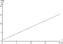
I notice that you're plotting hFE vs. Ib, did you also plot versus Ic?
Pete B.
Since I have no way to find RC, following andy_c, I have put RC=0.
I have checked (using LTSpice) that (1/IB,VBE/IB) are on a straight line, and that, if RC=0, the intercept with the "VBE/IB" axis is RB.
I came into this conclusion reading the Agilent papers, but I have no formal proof (or I'm unable to repeat the Agilent reasonings) of it.
The experimental points are well aligned.
In the graph I provided there is also hFE vs/ IC.
My method doesn't work all the times: I'm having problems with the MJE15030 ... and I don't understand why (the difference).
Attachments
teodorom said:Since I have no way to find RC, following andy_c, I have put RC=0.
I have checked (using LTSpice) that (1/IB,VBE/IB) are on a straight line, and that, if RC=0, the intercept with the "VBE/IB" axis is RB.
I came into this conclusion reading the Agilent papers, but I have no formal proof (or I'm unable to repeat the Agilent reasonings) of it.
The experimental points are well aligned.
In the graph I provided there is also hFE vs/ IC.
My method doesn't work all the times: I'm having problems with the MJE15030 ... and I don't understand why (the difference).
Yes, RC is a compromise since it is lower in saturation, however I'm not too concerned if Vce sat is a volt or so off, in fact there is often a wide range of .5 to 1.5V or more for typical vs. max value for Vce saturation in power transistors. Andy used a value of .06 ohms for Rc which provides a much more reasonable match over most of the operating range.
Seems something under .1 ohms is about right for most typical 10 to 20A power transistors with low Vce sat.
Obvioulsy, RC effects the hFE curve since for example with 1 ohm the max Ic is limited to 5A with Vce=5V and 20A with Vce=20V, no matter how large the Ib. The effect is less with smaller RC values but it does come into play. The value was completely off, being 2 ohms in the OnSemi model.
Pete B.
- Home
- Design & Build
- Software Tools
- Spice simulation