Prasi:
I have, for an integrated amplifier built for my younger daughter. Your version was released at just the right time: she wanted a very compact chassis and the very limited amount of available space was too small for the Store's speaker protection board. Yours just barely fit. She loves her new stereo. While I understand that doesn't amount to a ringing endorsement of any particular aspect of the project, I am certainly pleased and will be using your design in all my amplifier projects.
Regards,
Scott
I can't be the only person to have built V3 boards recently. I have gone over every component on my stuffed board while comparing it to the silkscreen on a second copy of the same PCB and every diode, transistor, and capacitor are right way around. I have gone back over every comment about part substitutions, pinout of transistors, and carefully matched to the published BOM. I have tried to follow the signal around the PCB while referring to the schematic but I will admit i am having a hard time flipping the PCB back and forth and keeping the traces straight. Can anyone give some insight to the point Mooly brought up?Can someone who has built this confirm which of these is correct. V2 and V3 diagrams have different transistor location numbers. T4 in V2 becomes Q5 in V3. All other references seem the same apart from switching from T to Q designators.
I puzzled over this for a moment as in the post above as T4 would have no obvious means of burning but Q4 in V3 does.
View attachment 1349124
View attachment 1349126
Analogico:
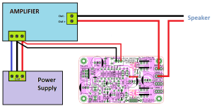
No. While your schematic would permit the speaker protection board to operate as intended while the amp is operating, it would be better if the speaker protection board to power down before the amp's power supply is exhausted to eliminate any potential "thumps" when the amp is turned off. Prasi's speaker protection board (like the Store's board that inspired it) should be powered either from the AC supply feeding the amp's power supply or from a much smaller single rail DC supply (i.e., a supply with very little capacitance).
Regards,
Scott
Scott,
I see! Your explanation makes perfect sense.
I was thinking of using the speaker protection board in an amplifier with an external power supply and I didn't want to use a transformer (however small) in the amplifier chassis.
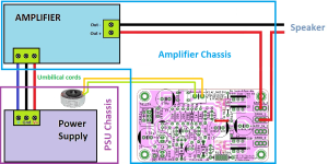
I think the solution will be to put a small stand-alone transformer (15VA - 2 x 12V) in the power supply chassis to power the speaker protection board. The connection between the chassis will be made with umbilical cords, as shown in the drawing below.
Many thanks.

Analogico:
I think there are two better alternatives to your approach. Unless there is a compelling reason why the existing transformer cannot power the speaker protection board, I wouldn't bother with a second transformer. The first alternative is to connect the speaker protection board to one of the two pairs of secondaries feeding your amp's power supply. Tapping into that secondary to power the speaker protection board, which has a bridge rectifier, won't adversely affect the amp. The second approach would be to add a small second power supply (as mentioned in my post above) between one of the amp's two pairs of secondaries and the speaker protection board. I've done this with several projects -- usually four 1N4007 diodes and a tiny CRC filter with perhaps 1200 uF in total capacitance -- and it has performed very well for me. That said, I am no engineer. You can undoubtedly get better advice from the more experienced members.
Regards,
Scott
Scott,
I appreciated your suggestions. The first alternative is interesting because it is functional and the simplest of all. But the second alternative I don't understand so well. In your opinion, what would be the advantage of adding a small power supply, when adding a small transformer is much simpler (at least as I see it), especially if you already have that small transformer at hand?
Thanks.
Analogico:
Well, as to the first alternative, it provides the exact same benefit as your adding a second transformer (assuming their secondaries are the same). I doubt that adding the tiny power supply has any material effect. I just enjoy adding it, it does no harm, and it makes verifying that the proper voltage is being delivered to the speaker protection board easier.
Regards,
Scott
Switch off should be pretty quick.
Will a SSR be OK... I think it depends a lot on whether the preamp output can drive any capacitance the FET's present. I'm also wondering about 'off' resistance. There is also quite a lot of capacitance from input to output which is of no concern for a low impedance speaker but would be for a preamp. It means high frequency signals will still pass.
I would probably say a better option is to use a relay tbh and even better would be a simple redesign to use the relay in shunt mode so it shorts the output when it is muted.
This shows the off time. The supply is cut at exactly 42 seconds:

And zoomed in:

Will a SSR be OK... I think it depends a lot on whether the preamp output can drive any capacitance the FET's present. I'm also wondering about 'off' resistance. There is also quite a lot of capacitance from input to output which is of no concern for a low impedance speaker but would be for a preamp. It means high frequency signals will still pass.
I would probably say a better option is to use a relay tbh and even better would be a simple redesign to use the relay in shunt mode so it shorts the output when it is muted.
This shows the off time. The supply is cut at exactly 42 seconds:
And zoomed in:
For that I need some help. My diy tube amp do not have mute function yet.I would probably say a better option is to use a relay tbh and even better would be a simple redesign to use the relay in shunt mode so it shorts the output when it is muted.
The easiest way would be to use two SPDT relays. The centre common connection goes to ground and the set of contacts that is normally closed (when the the relay is not powered) go the preamp output. When the relay turns on the contacts open and the short on the output is removed.
Like this. The normally closed contact connect to the preamp output and grounds it (muted) and when the relay opens the preamp output has the 'short' removed. The other terminal is left unused.

Like this. The normally closed contact connect to the preamp output and grounds it (muted) and when the relay opens the preamp output has the 'short' removed. The other terminal is left unused.
For that I need some help. My diy tube amp do not have mute function yet.
I would do something like this:
https://www.diyaudio.com/community/threads/lx-mini-crossover-article.324747/post-5683587
If you do not want to make your own PCB or do it on e.g. veroboard, then it can be realised using this kit:
https://diyaudiostore.com/products/nelsons-psu-filter
You can use the PSU filter or not, just omit the irrelevant components and place jumpers as needed.
Edit: This solution do not give DC protection, if that is what you are after - only thump prevention on power on and off.
Last edited:
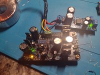
Not having much luck with DIY lately. I built the PRASI board version and dont seem to have start up delay or dc protection. I have double checked every component and compared to the schematic.
I tried increasing R15 all the way to 15kohm and maybe got a couple more milliseconds of delay. Currently with 470ohm resistor installed my voltage drop across that resistor is 9.05v.
For Dc protection I connected the negative of a 9v battery to the ground pin on the PRASI board and the positive to the "amp in" lug. The yellow power led stayed lit.
I have continuity between "amp in" lug and "spkr" lug as soon as I apply power. Maybe I am testing the dc protection incorrectly but I still have no delay on start up.
Attachments
It has been quite a while since I played around with electronics and this circuit seemed nice to start with and get the feeling back before moving on to building a new amplifier.
I have drawn the V3 schematic in LTSpice and I have breadboarded the flipflop-circuit to play around with. I used MPSA42's because that is what I had at the moment. I altered R1 to 1k8 because 1k is too low when using higher voltages, it would dissipate too much heat. I also used 10uF capacitors instead of 2.2uF, to make the blinking more relaxed. When I bring the cathode to ground on my breadboard, the LED indeed stops blinking.
However, in LTSpice it does not (I think). The blue graph shows the cathode of D5 being pulled to ground after +-5seconds, which is indeed what I expect.
At the same time I(R15) becomes 30mA, which simulates the relay coils being engaged.
V(n013) in red is the voltage at the anode side of the diode and base of Q2, which I can not figure out myself.
Could anyone explainn why V(n013) is what it is, and whether this is normal? Or what I did wrong in my simulation.
ILed (in green) looks to be blinking to me.

Thanks,
Brian
I have drawn the V3 schematic in LTSpice and I have breadboarded the flipflop-circuit to play around with. I used MPSA42's because that is what I had at the moment. I altered R1 to 1k8 because 1k is too low when using higher voltages, it would dissipate too much heat. I also used 10uF capacitors instead of 2.2uF, to make the blinking more relaxed. When I bring the cathode to ground on my breadboard, the LED indeed stops blinking.
However, in LTSpice it does not (I think). The blue graph shows the cathode of D5 being pulled to ground after +-5seconds, which is indeed what I expect.
At the same time I(R15) becomes 30mA, which simulates the relay coils being engaged.
V(n013) in red is the voltage at the anode side of the diode and base of Q2, which I can not figure out myself.
Could anyone explainn why V(n013) is what it is, and whether this is normal? Or what I did wrong in my simulation.
ILed (in green) looks to be blinking to me.
Thanks,
Brian
The LED should stop blinking in the sim but there does seem to be unwanted LED behaviour going on.
I tried my sim. Caps 47uF to slow it down. The fine 'noise' in the LED current when it should be off seems to be ripple current from the rail passed through the LED and diode to ground when the relay drive is active. The current would make the LED glow.

I tried my sim. Caps 47uF to slow it down. The fine 'noise' in the LED current when it should be off seems to be ripple current from the rail passed through the LED and diode to ground when the relay drive is active. The current would make the LED glow.
Hi JhoflandHere's the schematic, the layer by layer layout and the zipped Gerbers. The amplifier connections are set up for using faston spade lugs. The control power comes in on the three pin, 2.54mm pitch, connector.
is it possible that you send me your BOM? or post here the link to your project.
your PCB looks very fine for me. SMD is not a problem at all for me too.
kr
chris
It's been awhile since I did that design so I had to look back in the postings. November of 2018. I have done a number of different designs and variations since then which, in my opinion, are improvements. One of the more recent variations is available from XRK's Etsy store as a ready to use completed solution. I think He has sold more than 200 pairs over the last few years. If I can find the design you are referring to in my archives I'll regenerate the Gerbers and create a BOM. Alternatively, I can supply you with the schematic, Gerbers, and BOM for one of the more recent versions. One I've recently done for my own use mounts directly on the amplifier output binding posts and contains the circuitry for both channels on one board. Message me or send direct email to janhofland43"at"gmail"dot"com to tell me what you would like to have.
Hi Jhofland,
Thank you for your answer. I have the pcb at post 333 in my hands. so i want go with this. if you have updates or some improvements at this design that would be perfect but it should be handled with this pcb.
Thank you very much for your patient.
kr
chris
ps: i know very well the XRK SSR (done by you too). ordered several times. i want to try some small one 😉
- Home
- The diyAudio Store
- Speaker Turn On Delay and DC Protector Board Set (V3)

