In fact, that is not even the case for audio: for most cables, most of the audio spectrum will be well below the LF cut off frequency, meaning the amplifier will see a reactive load of up to -45°
The lf cutoff frequency of what? We speak of cables in the 10 foot range.
When the load impedance matches the line impedance, the amp will see only that impedance. If the cable is 8 ohm and the load is 8 ohm, the amp will see pure resistance. If the cable is 8 and the load is 150, the amp will see the cable capacitance.
jn
If the cable is 100ohm and the load is 5 to 50ohm, what does the amplifier see?
The amplifier will see the inductance of the cable.
For loads above cable z, the capacitive energy storage of the cable is dominant.
For loads below cable Z, the inductive energy storage of the cable is dominant.
For loads equa to cable Z, the inductive energy of the cable is exactly equal to the capacitive energy, and the summation of the two is a minima.
To examine these energy relationships, consider a DC signal from the amp to the load.
jn
This seems to confirm that interconnects at line level will present capacitance to the source. Much as many of us seem to understand.
But it also seems to confirm that speaker cables present inductance to the power amp.
This is not what many of us worry about. We regularly see us posting concerns about the added capacitance of speaker cables upsetting power amplifiers.
Can you offer an explanation of where I am misunderstanding?
But it also seems to confirm that speaker cables present inductance to the power amp.
This is not what many of us worry about. We regularly see us posting concerns about the added capacitance of speaker cables upsetting power amplifiers.
Can you offer an explanation of where I am misunderstanding?
This seems to confirm that interconnects at line level will present capacitance to the source. Much as many of us seem to understand.
But it also seems to confirm that speaker cables present inductance to the power amp.
This is not what many of us worry about. We regularly see us posting concerns about the added capacitance of speaker cables upsetting power amplifiers.
Can you offer an explanation of where I am misunderstanding?
It's part of the negative feedback thing. Capacitive loads change the phase of the feedback, and if sufficient, will change it to positive. I'm really simplifying, but look up amp stability with feedback. My first edition jung had a good chapter on it.
jn
The LF cut off of the characteristic impedance. The length doesn't matter here, because it is an iterative impedanceThe lf cutoff frequency of what? We speak of cables in the 10 foot range.
That is true above the cut off frequency, which could be anywhere between several KHz and several hundreds of KHz, depending on the cable construction (mainly the quantity of copper).When the load impedance matches the line impedance, the amp will see only that impedance. If the cable is 8 ohm and the load is 8 ohm, the amp will see pure resistance. If the cable is 8 and the load is 150, the amp will see the cable capacitance.
Above this frequency, the Zo is real and more or less constant, below it is variable and has an imaginary component, and is therefore impossible to match to a real fixed value like 8Ω.
That is impossible to determine without additional parameters: the frequency, of course, the length of the cable and its lineic parameters: capacitance, inductance and resistance. The fact that it is 100Ω only tells you about the ratio of L to C, not their absolute value, nor the value of R.If the cable is 100ohm and the load is 5 to 50ohm, what does the amplifier see?
Inductive loads also affect the feedback. But whereas capacitive loading decreases the phase margin, Inductive loading increases the phase margin.
I don't believe it's that that is causing me concern.
Most parallel twin core have a typical character impedance that is much higher than the typical speaker load.
Could the inductance presented by the cable be interacting with the capacitance of the load and thus canceling out, to leave a lower net impedance that the amplifier is left with trying to drive?
At the moment, the thought that speaker cables present inductance is confusing me.
The whole circuit that forms the speaker/s, crossover, cables and connectors is what the amplifier sees from it´s terminals, right?
So, if I change a cable (as I did), with a different capacitance, inductance and resistance, it will modify the way the amp. looks at this "Network". Or am I wrong?
That is why the sound of the speaker changed so dramatically?
So, if I change a cable (as I did), with a different capacitance, inductance and resistance, it will modify the way the amp. looks at this "Network". Or am I wrong?
That is why the sound of the speaker changed so dramatically?
But JN has already told us that when the load (badly) terminating the cable is of lower impedance than the cable's characteristic impedance, that the cable presents inductance to the source.That is impossible to determine without additional parameters: the frequency, of course, the length of the cable and its lineic parameters: capacitance, inductance and resistance. The fact that it is 100Ω only tells you about the ratio of L to C, not their absolute value, nor the value of R.
Cordell and Ott both mention RF terminating of low frequency cables. Is there a clue in their advice?
Yes, the amplifier sent a different version of the signal to the speaker.The whole circuit that forms the speaker/s, crossover, cables and connectors is what the amplifier sees from it´s terminals, right?
So, if I change a cable (as I did), with a different capacitance, inductance and resistance, it will modify the way the amp. looks at this "Network". Or am I wrong?
That is why the sound of the speaker changed so dramatically?
The amplifier's job is to send a (scaled) copy of the input signal to the speaker.
If we muck about with it's ability to do that, then it is our fault that it sounds wrong.
Broadly speaking, and since the wavelength of audio signals will always be much greater than any practical cable, yes, but as I said the characteristic impedance concept is of little use in audio, since it is highly frequency dependent and has an imaginary part: see for example fig 7 of this document:But JN has already told us that when the load (badly) terminating the cable is of lower impedance than the cable's characteristic impedance, that the cable presents inductance to the source.
Characteristic Impedance of Cables at High and Low Frequencies
It is for coaxial cables, but transmission lines theory remains valid whatever the medium: only the numerical values change, not the general behavior.
If you want to know with a certain accuracy what impedance the amplifier will see, you have to take everything into account.
Why not: at RF, the characteristic impedance will be stabilized, and matching makes senseCordell and Ott both mention RF terminating of low frequency cables. Is there a clue in their advice?
You need to model the line. Bateman found it was necessary to use 200 plus elements to accurately model a short length.The LF cut off of the characteristic impedance. The length doesn't matter here, because it is an iterative impedance
The only thing missing is G. L, R, and C per foot is adequate. The only changes resulting from inclusion of R in the equations is a rising of impedance at lower frequencies. Zips will rise about a factor of 3 to 4 in impedance at lf, and the prop velocity will also slow down to about 10% Vc.
As I said, use the DC energy storage numbers to get an idea what the amp sees.Above this frequency, the Zo is real and more or less constant, below it is variable and has an imaginary component, and is therefore impossible to match to a real fixed value like 8Ω.
Cyril wrote a really good paper, too bad it wasn't published.
jn
... but as I said the characteristic impedance concept is of little use in audio, since it is highly frequency dependent and has an imaginary part
Frequency dependence does not discount the concept. It does make it a bit more complex.
Nice link, btw..
Agreed..It is for coaxial cables, but transmission lines theory remains valid whatever the medium: only the numerical values change, not the general behavior.
in the frequency range below the amplifier's open loop unity gain frequency, all one needs to do is consider the amount of capacitive storage in the line which alters phase margin. For all intents and purposes, it is practical to use the dc capacitance of the cable for margin calcs..If you want to know with a certain accuracy what impedance the amplifier will see, you have to take everything into account.
It's to present a load at the end of the cable so that the cable doesn't appear as a capacitor to the amp. Some also use it to tame RF, as some amps are designed such that rf can intrude via the output ports..Why not: at RF, the characteristic impedance will be stabilized, and matching makes sense
jn
You need to model the line. Bateman found it was necessary to use 200 plus elements to accurately model a short length.
The only thing missing is G. L, R, and C per foot is adequate. The only changes resulting from inclusion of R in the equations is a rising of impedance at lower frequencies. Zips will rise about a factor of 3 to 4 in impedance at lf, and the prop velocity will also slow down to about 10% Vc.
As I said, use the DC energy storage numbers to get an idea what the amp sees.
Cyril wrote a really good paper, too bad it wasn't published.
jn
Hi jneutron,
These are good points. For some discussion of these effects and some data, some may find it useful to look at Chapter 18, especially pp. 375 & 376.
Cheers,
Bob
Hi jneutron,
These are good points. For some discussion of these effects and some data, some may find it useful to look at Chapter 18, especially pp. 375 & 376.
Cheers,
Bob
Thanks Bob.
Um, please pardon my ignorance. Chapter 18 of what book?
edit...Oh, duh...I see a thread on it...😱
jn
Last edited:
Thanks Bob.
Um, please pardon my ignorance. Chapter 18 of what book?
edit...Oh, duh...I see a thread on it...😱
jn
Sorry, my book, "Designing Audio Power Amplifiers".
Cheers,
Bob
Cyril wrote a really good paper, too bad it wasn't published.
jn
Part one is here:
http://www.waynekirkwood.com/Images/pdf/Cyril_Bateman/Bateman_Speaker_Amp_Interaction.pdf
I have part two too, but don´t know if I can post it here (copyright).
Last edited:
Part one is here:
http://www.waynekirkwood.com/Images/pdf/Cyril_Bateman/Bateman_Speaker_Amp_Interaction.pdf
I have part two too, but don´t know if I can post it here (copyright).
Ah, good.
Figure 8, page 7.
Shows an actual reflected audio signal with a speaker cable. Note that the delay is IIRC, 50 times longer than the cable's length and prop delay would lead us to believe.
It is a consequence of the horrid mismatches at both ends of the cable.
Unfortunately, not everybody has access to a reflection bridge.
Of note is the fact that this delay will "cusp" at zero (actually, double transit time) when the load matches the line.
I'm not sure if this is the article where he states the need for 200 plus elements to properly model the line..
jn
Last edited:
We seem to be once again co-mingling in-band and out-of-band transmission line characteristics. Of course a speaker cable does not have a single characteristic impedance. At low frequencies it's impedance is near infinite and only approaches it's advertised value near 100KHz.
Cyril Bateman Articles
Electronics World Magazine
Measuring Speaker Cables: 1 Cyril Bateman Dec 1996 p925
Measuring Speaker Cables: 2 Cyril Bateman Jan 1997 p52
Measuring Speaker Cables: 3 Cyril Bateman Feb 1997 p119
Cyril Bateman Articles
Electronics World Magazine
Measuring Speaker Cables: 1 Cyril Bateman Dec 1996 p925
Measuring Speaker Cables: 2 Cyril Bateman Jan 1997 p52
Measuring Speaker Cables: 3 Cyril Bateman Feb 1997 p119
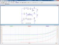
To put things in perspective, here is the comparison between three 40m cable models feeding a 8Ω purely resistive load. The cable has a characteristic impedance of 100Ω.
The impedance seen by the amplifier is plotted from 1KHz to 100KHz (below 1KHz nothing interesting happens) for an actual cable (green), an ideal transmission line having no LF effects (red), and a lumped model (blue).
Despite the 40m length, the effects remain relatively small, but it is interesting to note that the crude lumped model does better than the ideal transmission line, particularly regarding phase (dotted lines).
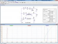
Next are the same parameters viewed with Nyquist. The markers are at 20KHz.
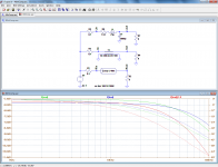
And finally, the frequency response seen by the speaker (the amplitude of the red trace has been scaled to more or less match the other traces)
The impedance seen by the amplifier is plotted from 1KHz to 100KHz (below 1KHz nothing interesting happens) for an actual cable (green), an ideal transmission line having no LF effects (red), and a lumped model (blue).
Despite the 40m length, the effects remain relatively small, but it is interesting to note that the crude lumped model does better than the ideal transmission line, particularly regarding phase (dotted lines).
Next are the same parameters viewed with Nyquist. The markers are at 20KHz.
And finally, the frequency response seen by the speaker (the amplitude of the red trace has been scaled to more or less match the other traces)
Attachments
Last edited:
- Status
- Not open for further replies.
- Home
- General Interest
- Everything Else
- speaker cable myths and facts