Thanks for all your help. Ill keep you updated if anything interesting happens. Btw im going to buy the npn transistors, do I also have to buy the matching pnp ones?
I have to buy the TIP142T's anyways because of the one I broke, so why not go ahead and place the order. Also I'm curious if by installing them the problem gets resolved.
Btw, I found the BDX33CG cheaper. Do you think I could substitute it for the TIP142T? Will they work well with the TIP147T?
Btw, I found the BDX33CG cheaper. Do you think I could substitute it for the TIP142T? Will they work well with the TIP147T?
Order if you want but if you find another fault, you may have to place another order.
I'd use the originals. The others may work but without testing thoroughly, there's no way to know if they will work perfectly.
I don't know what the problem is so I can't tell you if the problem will be resolved... by anything.
I'd use the originals. The others may work but without testing thoroughly, there's no way to know if they will work perfectly.
I don't know what the problem is so I can't tell you if the problem will be resolved... by anything.
Well I completed the long and painful test of each transistor in each location. I let it run 1-2 mins with 5-20 secs of music. All passed! Next up. Multiple transistors at once. If I want to test multiple transistors can I put them on the same metal heatsink/level without Kapton? Im thinking I can since the back of each transistor is connected to the collector legs and Q2-Q6 all have the collector legs connected in the pcb.
What are your thoughts on buying something like this to test the output transistors?
https://www.aliexpress.us/item/3256805949842595.html
https://www.aliexpress.us/item/3256805949842595.html
Wanted to share this great article on how bipolar transistors work and how to test them.
https://www.incbtech.com/articles/1...ipolar-transistors-how-they-work-art210e.html
Also this one on Darlington transistors:
https://www.incbtech.com/articles/1...lington-transistors-how-they-work-art067.html
https://www.incbtech.com/articles/1...ipolar-transistors-how-they-work-art210e.html
Also this one on Darlington transistors:
https://www.incbtech.com/articles/1...lington-transistors-how-they-work-art067.html
Here are my measurements. Not sure how much variance there should be among them:
Resistance:
Q2:
B-C: 1197k
C-E: open
B-E:13.6k
Q3:
B-C: 1220k
C-E: open
B-E:16.12k
Q4:
B-C: 1202k
C-E: open
B-E: 13.76k
Q5:
B-C: 1254k
C-E: open
B-E:13.04k
Q6:
B-C: 1212k
C-E: open
B-E:11.7k
Diode check (Left letter red probe - right letter black probe):
Q2:
B-C: .586
C-E: open
E-C: .451
B-E: .631
C-B: open
E-B: open
Q3:
B-C: .591
C-E: open
E-C: .453
B-E: .637
C-B: open
E-B: open
Q4:
B-C: .580
C-E: open
E-C: .452
B-E: .626
C-B: open
E-B: open
Q5:
B-C: .589
C-E: open
E-C: .454
B-E: .623
C-B: open
E-B: open
Q6:
B-C: .588
C-E: open
E-C: .453
B-E:. 633
C-B: open
E-B: open
Im trying to minimize the amount of times I heat the transistor pads. I already noticed a tiny corner of one of them lifting. So I think I'm going to wire the transistors up externally and test by adding one at a time. How much volume and for how long can I push audio through the right channel while it has less NPN vs PNP transistors installed? They will be heatsinked at all times.
Also you previously recommended a small resistor on the base leg. Do you still recommend that test?
Also you previously recommended a small resistor on the base leg. Do you still recommend that test?
Didn't you already test the transistors individually?
Did they ever produce DC output when off of the board?
The resistor is only going to be used when the fault can be reproduced.
Weren't you already using wires? That would have prevented the pads from being soldered and re-soldered. When desoldering the wires, you'd heat the wire only and not touch the pad.
The determination on how hard you can run the transistors is determined by how cool you can keep them. That said, you previously didn't need to run audio through them at all for the DC to be present (correct me if I'm wrong).
Playing them now (at a low level) would only be to be able to monitor the status of the amp without having to constantly look at the lamp or meter.
Yes I tested each transistor in each location individually, both with and without audio/speakers. No DC ever presented itself in all my tests. As you may recall a couple tests even went over an hour. When compared to my previous DC issues which occurred immediately or within seconds of powering up this is much improved behavior. Since removing them from the board and testing them "hard-wired" they have never presented any DC. But I have never tested more than one at time hard-wired. I thought adding audio would in some way push more circuitry in the amp and therefore could potentially trigger the DC voltage. (In the past DC occurred without any audio input or output)
As for the pads, yes I did use one set of 3 wires for my previous tests but it still required heating up the pads as I moved from location to location. I minimized it by testing all transistors in one location before moving to the next location. Again only one pad is slightly lifting and it belongs to Q2 which was my desoldering for dummies learning transistor and unfortunately got a lot of heat.
I'm off to add some transistors!
Im at 3 transistors and working good so far. I did notice a difference between the left and right channel. The dc voltage across the emitter resistors. The left channel is all -.5mv across the npn and pnp transistors. But on the right channel which only has 3 npn transistors installed and 5 pnp its -.7mv and -.3mv respectively. Does this tell us anything?
Those are insignificant. Ideally, all for the parallel group would be identical but due to tolerances and other variations in components, you'll see differences.
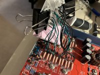
Well test is complete with all transistors and no dc occurred. Im going to keep running it for a few hours more. Here is a pic of the frankenamp. I decided to use a spackler instead of the level.
Also the emitter resistor voltage corrected itself with all the transistors. Each reads -.5mv.
Also the emitter resistor voltage corrected itself with all the transistors. Each reads -.5mv.
Attachments
Well Im a total loss here. It ran for hours, even with music, without any issues or dc voltage.
On a separate note, on the speaker that blew originally from the dc voltage I just noticed that the tweeter’s volume is very low
compared to the good speaker. The tweeter resistance checks out fine. Is it possible that the dc voltage damaged the tweeter without affecting the resistance? I thought the crossover would protect it but now listening to it and comparing it to the good speaker I think it may have been affected.
Well the amp continues to perform well. Its been running for many hours without any dc or other issues. I ordered some TIP142Ts and will soon put it back together and see.
On a side note Im the happy owner of an oscilloscope. Need some help testing it please. I think the trigger isn’t working well. Ive attached two pics of a 1khz waveform at different volumes. The higher the volume (and higher volts/div) one triggers well and is stable but the lower volume one (with less volts/div) is glitchy or jittery and jumps back and forth pretty much creating two waveforms.
On a side note Im the happy owner of an oscilloscope. Need some help testing it please. I think the trigger isn’t working well. Ive attached two pics of a 1khz waveform at different volumes. The higher the volume (and higher volts/div) one triggers well and is stable but the lower volume one (with less volts/div) is glitchy or jittery and jumps back and forth pretty much creating two waveforms.
Attachments
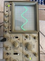
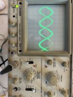
Did you adjust the trigger level when you had a smaller waveform on the display?
Look at the left of the displayed waveform. When you rotate the trigger level, the starting point of the waveform moves up or down if the trigger control is working.
Was the trigger LED lit when you had 2 waveforms?
Look at the left of the displayed waveform. When you rotate the trigger level, the starting point of the waveform moves up or down if the trigger control is working.
Was the trigger LED lit when you had 2 waveforms?
- Home
- General Interest
- Car Audio
- Soundstream Rubicon 502 with DC voltage in right channel