Hello guys, happy new year!!
New year, same problem 🙂
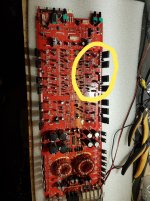
I have one soundstream 5 channel with a problem. First was in protection, the problem found on upper welding, now work, but on channel 1-2 have a power-on pop..
I have tried:
- isolated preamp= same pop
- exchanged with channel 3-4 all transistors and capacitors= same pop
This pop don't is always the same, sometimes is little, sometimes more bigger, not damage the speakers, but is udible.
What do you think?
New year, same problem 🙂
I have one soundstream 5 channel with a problem. First was in protection, the problem found on upper welding, now work, but on channel 1-2 have a power-on pop..
I have tried:
- isolated preamp= same pop
- exchanged with channel 3-4 all transistors and capacitors= same pop
This pop don't is always the same, sometimes is little, sometimes more bigger, not damage the speakers, but is udible.
What do you think?
OK. Thanks for the photo.
This appears to be one of the awful board designs. Is this a double-sided board with no vias?
This appears to be one of the awful board designs. Is this a double-sided board with no vias?
OK. Thanks for the photo.
This appears to be one of the awful board designs. Is this a double-sided board with no vias?
yes, exactly..
i have soldered all vias on the top and the bottom, this has solved protection mode, but not the pop.
i have other lil wonder amplifier, 2 channel and 4 channel but without power on pop...
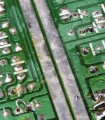
Soldering top and bottom is only a temporary solution, as it was from the factory.
To make it reliable, solder the top normally then use a short length of wire (or the leg from a new component that you install) to connect to a point on the bottom that's connected to the same trace. Do not solder the bottom pad where there is solder on top. See attached.
Have you found the muting transistor?
Is the pop before the mute delay ends?
Attachments
yes, i have used this metodSoldering top and bottom is only a temporary solution, as it was from the factory.
To make it reliable, solder the top normally then use a short length of wire (or the leg from a new component that you install) to connect to a point on the bottom that's connected to the same trace. Do not solder the bottom pad where there is solder on top. See attached.
not yetHave you found the muting transistor?
immediatly when power on, the muting transistors should be work fine, the music start 3-4 sec after power on.Is the pop before the mute delay ends?
don't is possible 🙁Can you ask the owner if the pop was an issue when the amp was new?
I'd suggest finding the muting transistors to see how bad the noise is before the transistors. It could be that an op-amp (or some other problem) is generating more noise than the muting circuit can stop. A weak ground on the muting transistors may do the same.
You could try disconnecting the signal feeding the noisy channels and removing the muting transistors to see if you still get the pop.
You could try disconnecting the signal feeding the noisy channels and removing the muting transistors to see if you still get the pop.
Thank you Perry.I'd suggest finding the muting transistors to see how bad the noise is before the transistors. It could be that an op-amp (or some other problem) is generating more noise than the muting circuit can stop. A weak ground on the muting transistors may do the same.
You could try disconnecting the signal feeding the noisy channels and removing the muting transistors to see if you still get the pop.
I have tryed, but i don't found traditional muting transistors! This is strange, but not found.... 🙁
I have checked all voltages, sine wave output, power supply square wave, should be all ok..
I have this problem also without all op-amp (removed)
What are they using for muting?
Some of the older SS amps used a delay in the CCS of the differential amplifier of each channel.
Some of the older SS amps used a delay in the CCS of the differential amplifier of each channel.
What are they using for muting?
Some of the older SS amps used a delay in the CCS of the differential amplifier of each channel.
Maybe... how can i check?
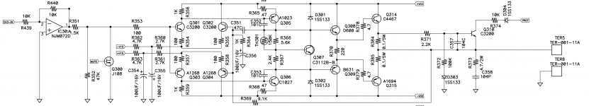
I found this (see attached). Does it have any J108 or J111 transistors?
If you can't find any jfets, we'll look into the CCS type muting circuit.
Exactly, i have find this muting jfet but no found.
Have you CCS type muting similar schematic for example?
Find the 4 differential amplifier transistors in each channel. They will have their emitters connected to 100 ohm resistors. Measure the DC voltage across those resistors before and after the mute delay. Does that voltage change.
Find the 4 differential amplifier transistors in each channel. They will have their emitters connected to 100 ohm resistors. Measure the DC voltage across those resistors before and after the mute delay. Does that voltage change.
Ok, i have found. I have measured voltage on this resistor. Is the same (approximatly) on all 4 channel. 0.01~0.09v without remote input, and when i turn on the amplifier, after 5sec i have 0.6v.
The drive circuit is the same for all channel (central optoisolator)
Are the op-amps in the amp or out of the amp, at this time?
Ah this time op-amp in the amp
- Home
- General Interest
- Car Audio
- Soundstream lil wonder 5.1000 power-on bump