And that's what I started with... until the 3 kg Faraday cage fell on my feet :-(To address EMI you need to screen and filter out the interference, put everything in a Faraday cage
Since then I've been looking for alternative solution. Now I have the stereo amplifier 2x0.5W (VCC=9V) in the light plastic case and I am very happy with it.

Exactly. The power transistors are driven with the current. When operating in the linear region, they produce almost no harmonics. The 2nd harmonic comes from T1, which is driven with the voltage.Only if voltage driven. But BJT can be quite linear if current driven like in this amp.
That's what you're doing when adjusting. Adjust roughly first, then adjust after 15 minutes and finally adjust after 30 minutes. When cold, the operating point is shifted by a maximum of 0.5V. The amplifier will also work quite well in this case.How do you keep the transistors at a constant temperature (so that you don't need to keep re-adjusting P1 and P2 as they warm up)?
And can you still measure the frequency response with your program?
I tried this myself with LTSpice. The cut-off frequency is 1.3MHz!
This is claimed for tube amps. But I don't like their bass. Here's something much better 😉Surprisinly wooly bass from nonexistant damping?
No correlation between wooly bass and low or nonexistant damping factor.Surprisinly wooly bass from nonexistant damping?
This supposed correlation results only from the combination of bad loudspeakers (e.g. multi-ways in large droning wooden cabinets) and unclean sounding amplifiers (mostly multistage complementary transistors push pull in the higher or very high power range)-;-)
Look for FETs in TO-220 FULLPAK packages. Try these.For me the FET transistors are not good enough, because their characteristics are non-linear.
The sound does not depend on "this" "addressed" "characteristic".
No correlation between wooly bass and low or nonexistant damping factor.
I guess this depends upon one's definition of a "wooly bass". The fact is, very low Df amps result in easily measurable and audible bass irregularities for the simple reason that such amps fail to maintain a constant voltage into a varying impedance load.
A set of speakers i use stay within 2 - 12ohms within the audible range, the Ltspice simulation above can easily illustrate the db variation in frequency response. My bet is on "spectacular" 🙂
That intentional bass boost at the speaker’s fs was used for decades to give the impression of solid bass from small to medium size (tube type) table radios, despite the poor baffling you’d get with the speaker. It actually served a purpose. Larger floor standing radios and console stereos could get the same effect - centered at lower frequencies of course. When those devices went “solid state”, that effect went away, leaving you to wonder “where’s the bass”?
The speaker’s inductive rise at high frequency would give the same effect as frequency went up, but was generally less dramatic. It still helped speech intelligibility.
The amplifiers couldn’t provide any more power into that high impedance region (less, actually) but even a 2 to 10 watt amp could get it loud enough in the bass for most sane people.
Simulation is much easier than soldering 😀
The circuit of the 12V amplifier:

The following FFT graph results for 1W:

The main thing is not to become addicted to the simulation, otherwise you will never know how the amplifier really sounds 😉
The circuit of the 12V amplifier:
The following FFT graph results for 1W:
The main thing is not to become addicted to the simulation, otherwise you will never know how the amplifier really sounds 😉
I tried this myself with LTSpice. The cut-off frequency is 1.3MHz!
Because it barely has any voltage gain with a 32 ohms load. (Changing the load to 1k more than tripled Vpp) Here are some stats. (I changed R4 to 220k to get slightly better numbers, plus the collectors to be at roughly 1/2 Vcc. This is one of the weirdest power amp schematics I've seen in a long time.
Attachments

I'm sorry, but you are incorrect.No correlation between wooly bass and low or nonexistant damping factor.
This supposed correlation results only from the combination of bad loudspeakers (e.g. multi-ways in large droning wooden cabinets) and unclean sounding amplifiers (mostly multistage complementary transistors push pull in the higher or very high power range)-;-)
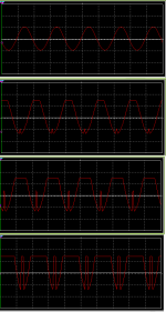
clipping reversal, very ugly😱I looked at how the distortion changes with signal level. It's definitely one of the more unusual ones with those reflections at negative peaks.
Might make an interesting guitar amplifier for a new (?!) distortion effect. Alas, I do not have an electric guitar, so I can't try that myself. However, now that I've seen the waveform I plan to breadboard it. May not have anything better than BD139/140 for the time being, but they should still be enough to drive a speaker with a 28V, 2-3 A supply.
And as said, most of the distortion comes from the input transistor T1 because it is driven with the voltage.Here are some stats
Possibly the different simulation programs use slightly different models for the transistors.I changed R4 to 220k to get slightly better numbers, plus the collectors to be at roughly 1/2 Vcc.
Thanks 🙂This is one of the weirdest power amp schematics I've seen in a long time.
If the preamplifier is supplied with the same operating voltage as this amplifier, this effect will not occur at all.I looked at how the distortion changes with signal level. It's definitely one of the more unusual ones with those reflections at negative peaks.
It won't be easy. You then need a preamplifier with an output signal of around 40Vpp. But in linear power range you can try this amp with guitar speakers quite well. For BD139/140 I would recommend a maximum of 12V. Around 1.5W through the guitar speaker it gets pretty loud.May not have anything better than BD139/140 for the time being, but they should still be enough to drive a speaker with a 28V, 2-3 A supply.
- Home
- Amplifiers
- Solid State
- Sound of the bipolar transistors