Just discovered I can now read the circuit diagram.
From what little I know about opamps, R135 and R136 should ideally have the same value. I suspect the cap values should also be changed but let's hope that doesn't matter too much. Watch out for oscillations that weren't there before.
Complicated compared to the datasheet, isn't it? The deviation from unity gain is encouraging. Sony may not have recalculated the optimum for the different sled arrangement.
To avoid the classic 'express train enters last station with no brakes' scenario, you should be ready to switch off without getting in a panic and electrocuting yourself.
Well, the train does not change behaviour at all🙂
Replaced R135 with a precision trimmer, cranked it up to 50k and down to around 21k - I hesitated do go further down -
and there was not much of a difference in the glitches.
A second trimmer is already built in to replace R136, but not connected yet.
Maybe you could give me a hint, why it is necessary to keep R136 the same value as R135,
because R136 is part of the positive input of the tracking coils opamp...😕
After replacing R135 and R136 with multiturn trimmers (both are now exactly trimmed to 33k, like the original resistors) I realized I can see the sleds gear turning easily - well they are constantly working and show no sign of any motion (or the lack of it) in rythm with the dropouts. So I guess the gear and sled work normal.
(But I have not played with R135 and R136 yet).
Breaking very, very slightly the spindle motor while playing results in similar sounding dropouts, but with higher dropout-frequency.
I wrote before, that replacing the heavy brass clamper with a clamper of lighter aluminium does not make a difference.
So if the disc motor was not working properly, mass was not the problem.
But maybe the disc rotates too slow as long as the player is cold, not because of mechanical difficulties, but of electronical difficulties.
So a dropout happens when RAM is emtied and the disck sppeds up to compensate.
The driver for the brushless, linear disc motor is again BA6297. I do not know wether this is logical, because as I wrote before, the glitches are more apparent,
after a disk was played in Back/fast FWD for some time
or when the laser jumps back from the last track backt to the first track. When a disk is stopped and started again, the glitches appear after 2 min- and disapperar after the player has become warm...
Last edited:
Well, the train does not change behaviour at all🙂
Replaced R135 with a precision trimmer, cranked it up to 50k and down to around 21k - I hesitated do go further down -
and there was not much of a difference in the glitches.
A second trimmer is already built in to replace R136, but not connected yet.
Maybe you could give me a hint, why it is necessary to keep R136 the same value as R135,
because R136 is part of the positive input of the tracking coils opamp...😕
Being quite new to this myself, that was my first impression, but R136 goes to so many places that it must surely be a ground point. The key is pin 7, which should be at VCC/2, acting as a virtual ground. The chip seems intended for single-supply operation, but in this circuit the GND pins are connected to the -ve supply, so VCC/2 should be true GND level. It's marked -0.2V. That's half-way between the GND pin and the VCC pin.
I think the usual practice of equal resistance to ground for both inputs of an opamp is so that the input bias current doesn't result in a differential voltage, and hence a DC offset at the output. I still find analogue solid state quite mysterious. The hard thing is to know when these kind of rules matter.
Hello PlasticIsGood,
thank you for your reply. Well, I played with R135 and R136 today, trimming both up to 36k and 39K for testing. Difference was that ratio of glitches rised while playing,
but this could as well be temperature related - placed the Sony at the open window to keep it cool before powering up.
Again played with tracking error signal and sled error signal, assuming that the resistors R101/102 and C104/C105 are low pass filters.
If correct, by default bandpass frequency for sled are 16hz and 22.6Khz for tracking/lens error. Put the resistor to 2/3 of original value, 10k/66.6kK /24hz/33.9khz, no difference.
Now everything is is back to default values.
There is a DC-offset Signal at Pin 26 of CXD2515 providing for the servo circuitry, but it looks like it can´t be altered.
So I guess playing with the opamps has come to a dead end, at least with my knowledge.
It is really strange, how predictable the glitches are. You can almost tune your clock to their 2-second rythm and once the player is warm to the touch (something around 30 degrees) they will be gone...
But at least spring is coming. Downside is in two weeks I will have to put the Sony in my fridge prior to testing...🙂
Last edited:
Have you checked the X-tal frequency for stability? (output pin 10 IC602). Just to confirm that this signal is not the culprit for all this. Just curious if this could be a kind of beat frequency produced by this type of synchronizing of the two frequencies 128fs coming from the DAC side and the 16.9344 Mhz x-tal, and that this is temp. related. 44.1 Khz times 128 equals 5,6448 Mhz. 5,6448 X 3 = 16,9344. That means that the oscillator is receiving a synch. input just every third x-tal osc. pulse
Looking at the block diagram of IC101, I see the output to the driver is converted to PWM. Because this is always either full on or full off, altering the gain will make little difference, unfortunately. There's no obvious way remaining of changing the relationship between radial motor and sled unless there are pins on the chip for that purpose.
The spindle motor servo system locks the reading frequency to the decoding frequency when playing. I can't see how it can drift at a constant rate, as it would if the motor were at the wrong constant speed. If you can measure frequency, or if you have a dual trace scope, you should be able to establish that the data rate from the disc (WFCK?) is related to RFCK as it should be. AFAIK, speed at start of play is determined by the free-running frequency of a PLL oscillator, which then locks on to the data rate.
If the glitch rate doesn't change with sled position then doesn't that point to a fault somewhere other than the mech? What happens to the eye pattern when a glitch happens?
Hello PasticIsGood and dacen!
Well, I do not see the glitches in the RF-Eypattern.
I have a very old, tube based 2-channel Philips Scope PM3231 which goes up to 15mHz.
I sometimes see the usual small dent in the upper edge caused by a scratch, but the glitches do not seem to cause anything.
Still, they are audible in alalog and digital out.
But the Scope is triggered by the eyepattern signal. I should probaly trigger the scope by an external signal like from SPDIF output.
I also have a frequency counter. Will try to measure the x-tal Frequency tomorrow and the relation of WFCK to RFCK with the scope.
All the best,
Salar
Last edited:
I did not have much time today to check. I would have to disassembly the servo bord to solder in a wire for measuring the xtal, so i measured RF-PLL Free Run, according to manual:
With the YEDS-18, frequence is steady something in between, 4.32175 and 4.32185. With other CD´s, range of fluctuation ist greater, 4.3216 /4.13219.
Interestingly, YEDS-18 does nit seem to show glitches, but it has bekome warmer- can´t keep the X5000 as cool as yesterday.
Checked WFCK and RFCK, using SPDIF as trigger for the scope.
I guees, RFCK is the fixed frequency, whereas WFCK is disk dependend
They WKCK wobbles against RFCK , more on a "normal" CD, lesser with YEDS-18.
But they do not shift against each other over time.
So I guess, frequency of pits and lands on a CD is crucial.
And whereas YEDS-18 is just perfectly manufactured, any slight variance from that causes the glitches.
I now can confirm, that the sync signal the CD produces (it seems to be signal from pin 73, WFCK, it can be measured at test connector CN514) influences the glitches.
With the reference Test CD YEDS-18, once used by Sony technicians to adjust CD-Players, it WFCK flutters the least, and almost no glitches playing YEDS-18,
when the player is cool, maybe one in two minutes.
Besides, the opening Song of this YEDS-18 (the rest are testsignals and a classical piece) is the most horrible music ever written.
All drum-machine and synthesizer horror of the eighties thrown together in 3´34 minutes.
So if your player returns unrepaired, the service technians simply could not bear to listen to YEDS-18 any longer 🙂
All other CD´s I tested, some brand new, produce the two-second-glitches this thread is about.
And they all produce a more jittery WFCK signal than YEDS-18.
Also RF-PLL Fre Run Frequency Check (page 10 in the manual) indicates this.
With YEDS-18, the frequency of 4.3218MHz is more stable than with the other CDs.
About the proposal measuring the stability of the xtal:
Is there any other way to measure the sync signals produced by the X601 besides taking the player apart -again- and soldering a wire to pin 63 of IC101 or pin 10 of IC 602?
I.e measuring XPLCK at connector 513?
Maybe somebody could tell me what the signals besides WFCK / RFCK at test - connectors 513 and 514 mean?
"DFCT" at CN514 seems to be the error signal caused by scratches or defects...?
Well, it has almost become too warm to go on measuring.
The X5000 now reaches "operating temperature" after a quarter on an hour.
Guess after the weekend, we´ll have to continue this thread next winter...
All the best,
Salar
Last edited:
I found with my CDP XA7ES the following:
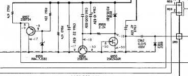
If the ripple on main cap of the display Power supply is above ~ 5Vpp the player starts to click on the analog output, without leaving a trace on the eye pattern! I attached the display power supply (VFD supply) of the cdpx5000 and CDP XA7ES. For the cdpx5000 R974 (22k) is way to high, as this resistor has to take base current of Q971 and leakage current of C972(22yF) - I tend to call this a design error, in my Sony it is 2.2K. So I recommend to put a 3.3k parallel to R974 and raise the main cap C971 to 680yF. Moreover this cap and the rectifier diodes have a strong impact on sound, so best take a silmic. I would replace the rectifier diodes D971-974 to 1A/100V Schottky diodes - smoother sound for some cents..
Do not ask me why Display current leads to clicking - I do not know, but checked it several times...hope this helps, philipp
Attachments

Hmm, every input is very welcome. Don´t hesitate to make a posting. Some times a fault has it´s mysterious ways.
Very true..I think the multiplexing circuit of the VFD tube leads to a critical noise voltage drop on the shared main ground bus, thus influencing some digital parts..have fun, Philipp
I guess I´ll have to wait to October to check this😀
- my flat (under the roof) alredy reaches about 23 degress celsius whereas is about 18 degrees celsius outside - too warm to provoke clicking...
- my flat (under the roof) alredy reaches about 23 degress celsius whereas is about 18 degrees celsius outside - too warm to provoke clicking...
Last edited:
sound will improve considerably with schotky diodes and good cap - the 22k will lead to an unstable regulator - it is intended to low pass filter the zener noise but e.g leakage of the 22yF cap will change with aging and : temperature! - so reference voltage for the regulator will change accordingly..
Yes 1000yF/63V is o.k...in my Sony I first took a 470yF Panasonic FC (clicking disapeared completely) but I disliked the harsh upper midrange , which is typicall for this type..silmics are more pleasing..good luck
Did replace R974 with 2,2k and C971 with 1000µF/63V - and put the player in the fridge (for this purpose, the design comes handy🙂, but don´t do this at home, remember moisturization)
No change, It still clicks when being cold. Could be that the warmup/noclick time has become shorter, but I would not bet on this.
Still, thanks a lot!
All the best, Salar
No change, It still clicks when being cold. Could be that the warmup/noclick time has become shorter, but I would not bet on this.
Still, thanks a lot!
All the best, Salar
Hello Salar, do not give up...
Given the small money necessary I would change the remaining three caps in the VFD PSU (C972/C973/C974) and keep the values as in the circuit diagramm..take a look at the voltages with an oscilloscope and watch out for high ripple..for testing purpose I would shorten the fuese resistor R902..voltage drop across R974 should be less than 0.2V..
good luck...Philipp
- Home
- Source & Line
- Digital Source
- Sony X5000 troubleshooting