Thanks Dennis. these are what I have. Fairchilds I think. Are there suggested alternative values for the resistors?
Pass DIY Addict
Joined 2000
Paid Member
That's a pretty nice PSU, Berny! With just a CRC, I measured 0.07 mV AC ripple on the speaker terminals. This is one VERY quiet amp!
Jim, there's a dependency on the Idss of the jfets. If your parts are at the upper
end of the B/BL grade range then may already be fine.
So for now assume you can't adjust the bias current sufficiently high.
Changing out P3 and P4 to 1K is probably the most 'universal' solution though
desoldering pots is a pain. An alternative is to change out the fixed resistors
R34/R35 which should be easier to desolder. You can measure the voltage
drops across R34/R35 to back out the jfet Idss. Once you have that info, you can
work out new R34/R35 values.
Thanks Dennis. I’ve ordered some trimmers and will order some replacements for R34/35. I guess 500r? I’ll try getting the pots out first.
Question, do the Mosfets need matched? And is there any benefit to tracking down 2sk2013/2sj313? Other than avoiding desoldering parts and adjusting biasing approach.
Question, do the Mosfets need matched? And is there any benefit to tracking down 2sk2013/2sj313? Other than avoiding desoldering parts and adjusting biasing approach.
Matching is not needed for proper operation though some may prefer to use NN and PP
pairs for the two channels. I think you got your kit from the diyaudio store and I
suggest sticking with the Fairchilds. (Lots of excellent builds with those already, plus
the Toshibas are hard to find.)
If you're ordering resistors, maybe both 500R and 750R and choose based on Idss
measurements?
pairs for the two channels. I think you got your kit from the diyaudio store and I
suggest sticking with the Fairchilds. (Lots of excellent builds with those already, plus
the Toshibas are hard to find.)
If you're ordering resistors, maybe both 500R and 750R and choose based on Idss
measurements?
Thanks Dennis
Yes I got the kit from the DIY audio store, in the first round of kits.
I've ordered the resistors you suggest plus 1K trimmers.
Would you suggest replacing the trimmers AND R34/35?
Also is there a way to identify idss prior to installation in the circuit?
Yes I got the kit from the DIY audio store, in the first round of kits.
I've ordered the resistors you suggest plus 1K trimmers.
Would you suggest replacing the trimmers AND R34/35?
Also is there a way to identify idss prior to installation in the circuit?
Last edited:
Just a triple check before I stuff JFets, BJTs and Mosfets, I'm working with the DIY Audio kit, first round.
Q1 - LSK170
Q2 - LSJ74
Q3 - ZTX 450
Q4 - ZTX550
Q5 - FQ3P20
Q6 - FQP3N30
Confirmation much appreciated! And also to check that legendinf on PCB matches the orientation for these?
Thanks!
Jim
Q1 - LSK170
Q2 - LSJ74
Q3 - ZTX 450
Q4 - ZTX550
Q5 - FQ3P20
Q6 - FQP3N30
Confirmation much appreciated! And also to check that legendinf on PCB matches the orientation for these?
Thanks!
Jim
Last edited:
Correct.
Q1 n-jfet k170
Q2 p-jfet j74
NPN for Q3 and PNP for Q4, so
ZTX450 for Q3 and ZTX550 for Q4
I can also confirm that Q5 (left position when looking at the pcb) must be P channel, so either 2SJ313 or FQP3P20. Q6 (right position) must be N channel, so either 2SK2013 or FQP3N30.
Q1 n-jfet k170
Q2 p-jfet j74
NPN for Q3 and PNP for Q4, so
ZTX450 for Q3 and ZTX550 for Q4
I can also confirm that Q5 (left position when looking at the pcb) must be P channel, so either 2SJ313 or FQP3P20. Q6 (right position) must be N channel, so either 2SK2013 or FQP3N30.
Just be careful with the ZTX450/ZTX550 since the "round side" isn't as obvious
as with TO92 parts.
Since your jfets aren't installed yes, can you try measuring their Idss?
as with TO92 parts.
Since your jfets aren't installed yes, can you try measuring their Idss?
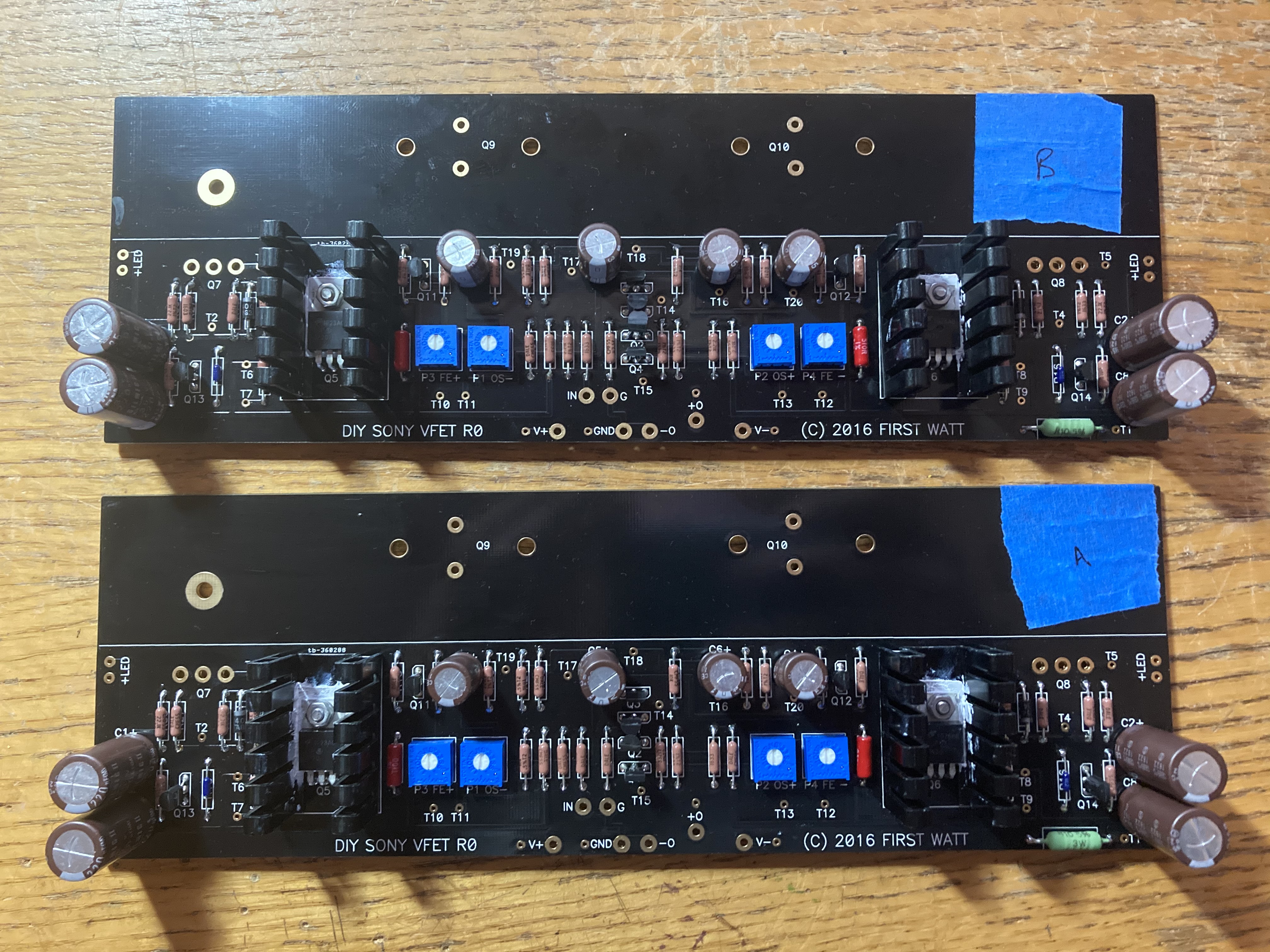
Thanks for verifying Rodeodave!
I think I've got the ZTX450/550 right, look ok Dennis?
I stuffed them before your post so they're now in the board. How do I go about testing IDSS?

I think I've got the ZTX450/550 right, look ok Dennis?
I stuffed them before your post so they're now in the board. How do I go about testing IDSS?
Last edited:
Looks fine.
Since the jfets are already in the boards, just continue on.
You can find out the Idss during power up when by measuring the
voltage across R35/R34.
Since the jfets are already in the boards, just continue on.
You can find out the Idss during power up when by measuring the
voltage across R35/R34.
I'm getting ready to build one of these amps. I have the boards from the DIY store but the "T" brackets are no longer available. I can make some but it would be helpful if there's a drawing that shows the location of the holes. I'm sure I can determine it but am being lazy and thought I'd ask.
I'm getting ready to build one of these amps. I have the boards from the DIY store but the "T" brackets are no longer available. I can make some but it would be helpful if there's a drawing that shows the location of the holes. I'm sure I can determine it but am being lazy and thought I'd ask.
Here.
I saved them from this thread.
Though I think holes for mounting bracket to UMS heatsinks should be 3mm.
Attachments
Here.
I saved them from this thread.
Though I think holes for mounting bracket to UMS heatsinks should be 3mm.
Thank you very much.
- Home
- Amplifiers
- Pass Labs
- Sony vFET Illustrated build guide