Sure. You'll need to tweak all four pots as you bias up the output stage to keep everything
in balance. So just get the front end reasonably close (1.4V is plenty) as a starting point for
the output stage biasing.
in balance. So just get the front end reasonably close (1.4V is plenty) as a starting point for
the output stage biasing.
Thanks Dennis. Tbh I’ve just stuck with around the 1.5v as per the schematic.
Any thoughts on a fast blow fuse/lamp limiter?
Also the channels boot closet to 1.6v and settle to 1.5v after a couple of minutes. All good I’m guessing?
Any thoughts on a fast blow fuse/lamp limiter?
Also the channels boot closet to 1.6v and settle to 1.5v after a couple of minutes. All good I’m guessing?
Last edited:
In general, I consider the use of a bulb limiter as an initial test.
You power up for a short time with one to look for signs of trouble and then
turn it off.
On the test fuse, the project article contains this info:
"I also suggest that you start out with the lowest possible line fuse that can
survive the modest inrush provided by the Variac. 1 amp fast blow is a good
start, and has a reasonable chance of protecting the circuit.
If you don't have a Variac, you will probably need a higher value, but keep it at a
minimum until you know the circuits are OK."
You cannot bias an amp with the bulb tester in place. And since you're
not using a variac, you may not be able to use a very small value test fuse,
because it has to survive the power up inrush current. You may have to
experiment a bit here.
If the initial T16, T17 output vfet bias voltages are set up correctly,
you should see a very small total current draw. (The higher the bias
voltage, the lower the current) I would expect just a few mV across
R32.
Also, no problem with the bias changing a bit at start up before
settling down.
Last edited:
As Dennis mentioned, the dim bulb limiter is for initial power-up only. It is used in case there is a short situation that would cause excessively high current to be drawn which may blow some components. If the initial power-up does not show any excessive current draw, power down and remove the dim bulb tester and connect the amplifier directly to the power outlet.
During adjustment for bias and offset with VFETs installed, do it in steps with time in between for warmup and stabilization, as rumina stated. Temperature will affect the adjustments so keep the amplifier case cover on in between adjustments. To make an adjustment, take the cover off, quickly make the adjustments. Do not try for perfection, just adjust enough to get closer to the goal, then replace the cover and wait for the temperature to stabilize. And then repeat. It is best to have three or more meters attached during this whole time so you can see the effects of your adjustments. The adjustment of one pot will affect the others. Make small adjustments each time.
Small adjustments are important. With single turn pots, small movement of the pots can cause large movements in voltage. rumina stated that it was easier the second time and I totally agree with him. Follow rumina's suggestions. Pay attention to the meters during each pot adjustment to see what changes.
Thanks Ben and Dennis, that's very helpful!
Unlike the pics on page 1 I've inly got 9 nylon insulators. I'm guessing the intention is to use these for the legs of the VFets and skip them for the screws as the heatsink is anodised and the screws don't risk coming into contact with it in the way they are oriented?
Should I order more of these or forge ahead? I do know this is a really silly question....
Last edited:
I prefer insulation on all pins/bolts
You can order some more of the insulators though finding the right size might
be tricky. You can try contacting the store and see if they can send you
some, or at least get your the correct size/part number.
Perhaps some insulating tubing for the pins? You would
want something that can take a bit of heat from soldering the pins.
Would heat shrink tubing work here?
Thanks Dennis, I found the part at mouser and ordered an equivalent here in the UK, slightly larger inner diameter at 3.7mm v 3.2mm but the other dimensions are the same.
I found these unused boards from a previous amp build.
If I tap one of my 22vac secondaries it won't detriment power to the amp boards too much will it? Or should I perhaps be looking to add a second transformer.
Soft start looks to be a good thing re in-rush currents too.
Soft Start & Speaker Turn-On Delay / DC Protector Combo – diyAudio Store
I assume you're talking about the speaker turn on delay board? The current draw is
minimal so no problem tapping off an existing secondary.
What are you using currently for soft start? Just thermistor (e.g. CL60)?
If you want to use that soft start board, I would suggest using a properly sized,
current limit thermistor instead of the bank of parallel power resistors, since
such a thermistor is designed to take the power continuously.
Yes I’m using CL60. I’ll maybe stick with those then.
Sorry yes I meant the DC speaker protection board. I guess it’s really just powering relays so shouldn’t be an issue. Thanks Dennis.
Sorry yes I meant the DC speaker protection board. I guess it’s really just powering relays so shouldn’t be an issue. Thanks Dennis.
Thanks Ben and Dennis, that's very helpful!
Unlike the pics on page 1 I've inly got 9 nylon insulators. I'm guessing the intention is to use these for the legs of the VFets and skip them for the screws as the heatsink is anodised and the screws don't risk coming into contact with it in the way they are oriented?
Should I order more of these or forge ahead? I do know this is a really silly question....
It is best to use the insulators on the screw holes. The screws are much larger diameter than the VFET pins. The screws will centre the pins in the holes so the likelyhood of the pins contacting the Tee is less. However it is best to insulate the VFET pins with shrink wrap. That is what I did on my build.
By the way I believe the kits were mostly shipped with eight insulators. See these posts:
Sony Vfet Illustrated build guide
Sony Vfet Illustrated build guide
Thanks Ben
The more I thought about it the more it made sense that the stand offs go with the screws. It struck me as well that the standoffs may not be too fond of the heat from the iron.
Anyway suffice to say I’ve built the amp up and am biasing one channel now. Got 100mv across r32, -6mv at the outputs and around 60mv at t18. The lid is on and the amp is pretty warm. Will leave it for a while and see what’s what. Seems pretty stable right now though.
I’ll get to the next channel in an hour or so.
Thanks Ben and Dennis, that's very helpful!
Unlike the pics on page 1 I've inly got 9 nylon insulators. I'm guessing the intention is to use these for the legs of the VFets and skip them for the screws as the heatsink is anodised and the screws don't risk coming into contact with it in the way they are oriented?
Should I order more of these or forge ahead? I do know this is a really silly question....
I bought this nylon insulators:
50pcs M3 M4 M5 M6 M8 White Nylon ABS Non Threaded Spacer Round Hollow Standoff Washer ID 3mm4mm 5mm 6mm 8mm PCB Board Screw Bolt|screw bolt|8mm boltbolt 8mm - AliExpress
Go for (M3 ID 3mm) + (5mm)
Good for M3 bolts/screws.
I also bought M4+5mm from this seller. And they appear a bit wider than 7mm and did not fit.. ) so don't buy them.
Perhaps some insulating tubing for the pins? You would
want something that can take a bit of heat from soldering the pins.
Nylon probably could melt if VFET pins touch it when solder.
I also bought PTFE tube I can cut.
1Meter 1mm 2mm 3mm 4mm 6mm 8mm PTFE Tube For 3D Printer Parts Pipe Bowden J head|for 3d printer|teflon tube 4mmteflon tube 6mm - AliExpress
Go for (ID2mm OD3mm) + only color is White.
Attachments
Last edited:
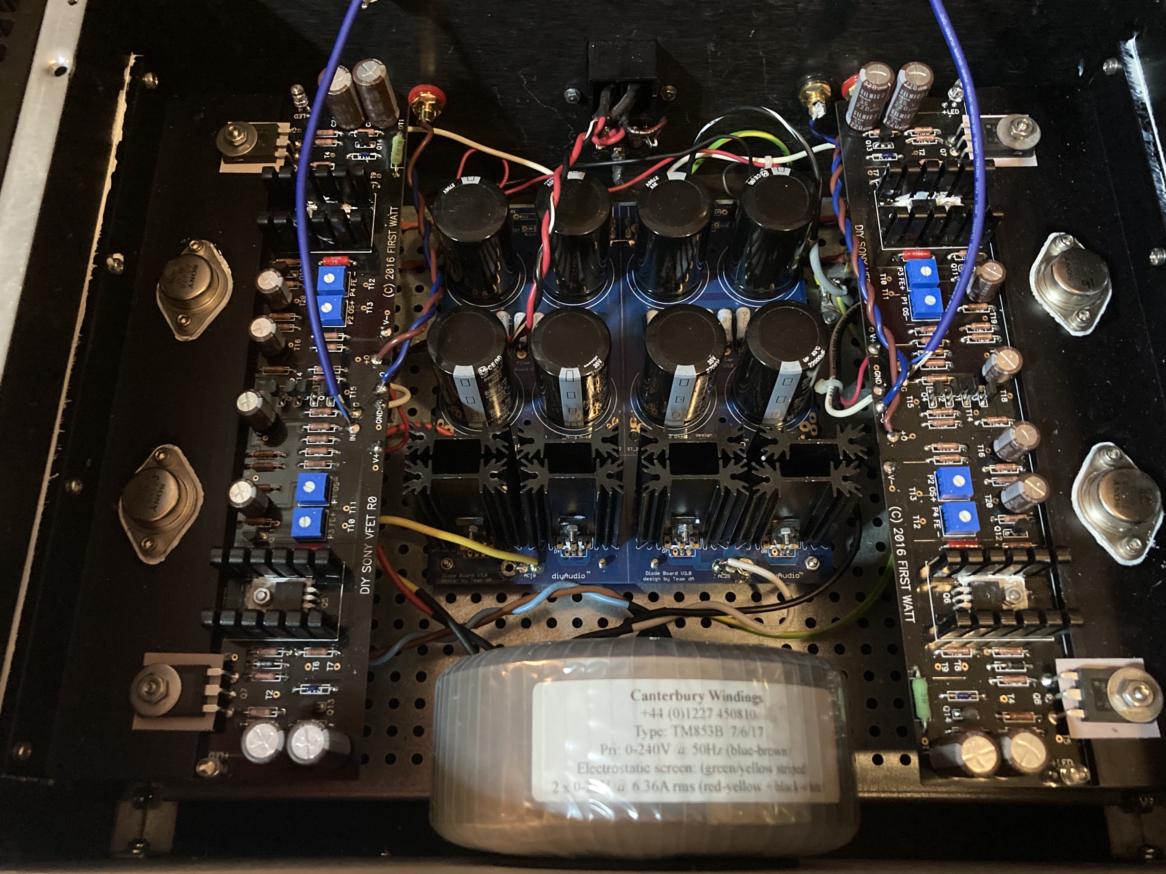
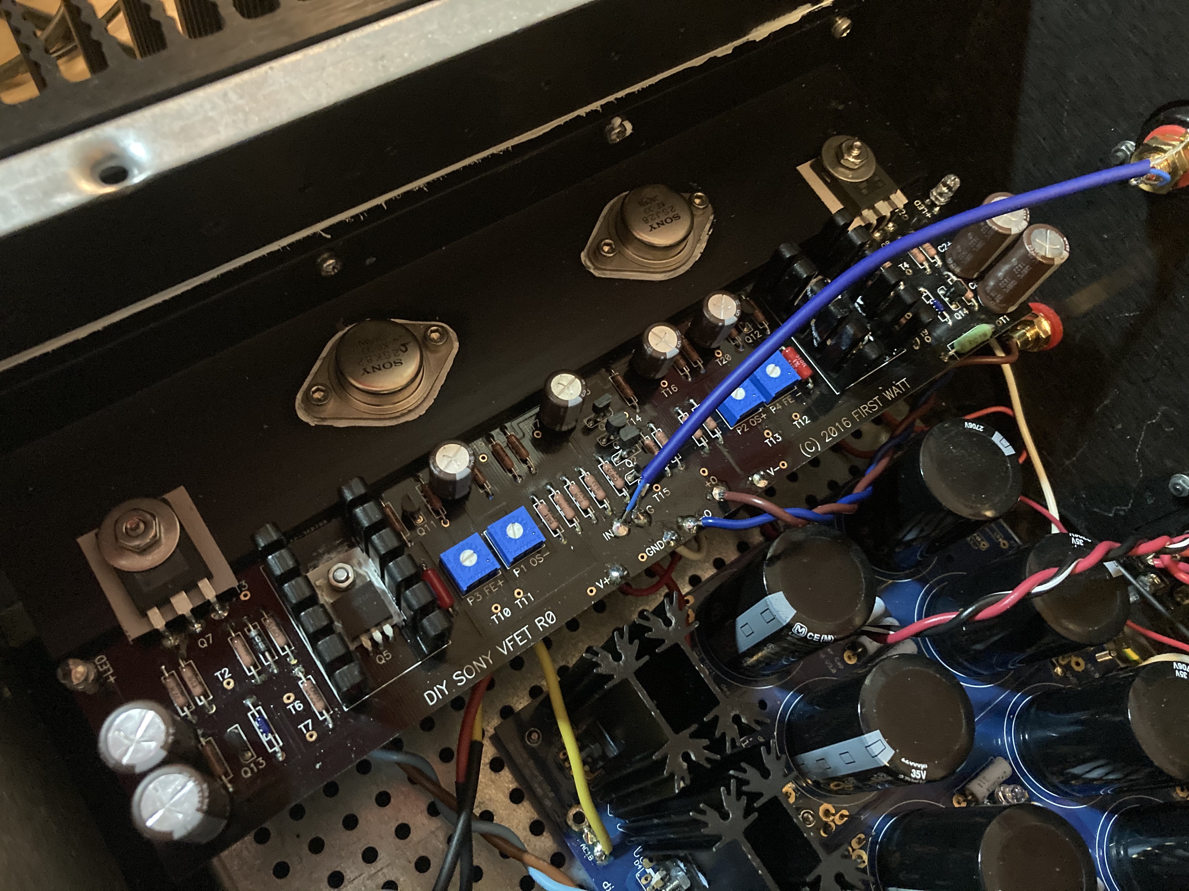
Ok I’ve got a working amp. Offset on 1 channel is pretty steady at 10mv, the other channel sits around 30mv. I may try to dial this channel in a little more.
Anyway last night I started with super cheap speakers and worked up to my main set. Sounds great! More listening today.
Big thanks to Papa Nelson Pass for sharing his stash and designing another incredible amp.
Thanks to Jim for this build guide. Sterling work as ever and an invaluable resource.
Special thanks to Dennis Hui and Ben Mah for getting me through the build without releasing the unobtanium 40 year old magic smoke, and for patiently answering all of my questions. I owe you guys a beer. When I make it to Canada I’ll deliver on that.
Last edited:

Congratulations! Please post some photos when you have a chance. (Or as the
Mighty Zen Mod would say, "No Porn, no glory" 🙂 )

Mighty Zen Mod would say, "No Porn, no glory" 🙂 )
Pics here. One side has under 10mv DC offset after warm up, the other is around 25mv. I may try to tweak this down a bit once the amp settles in.
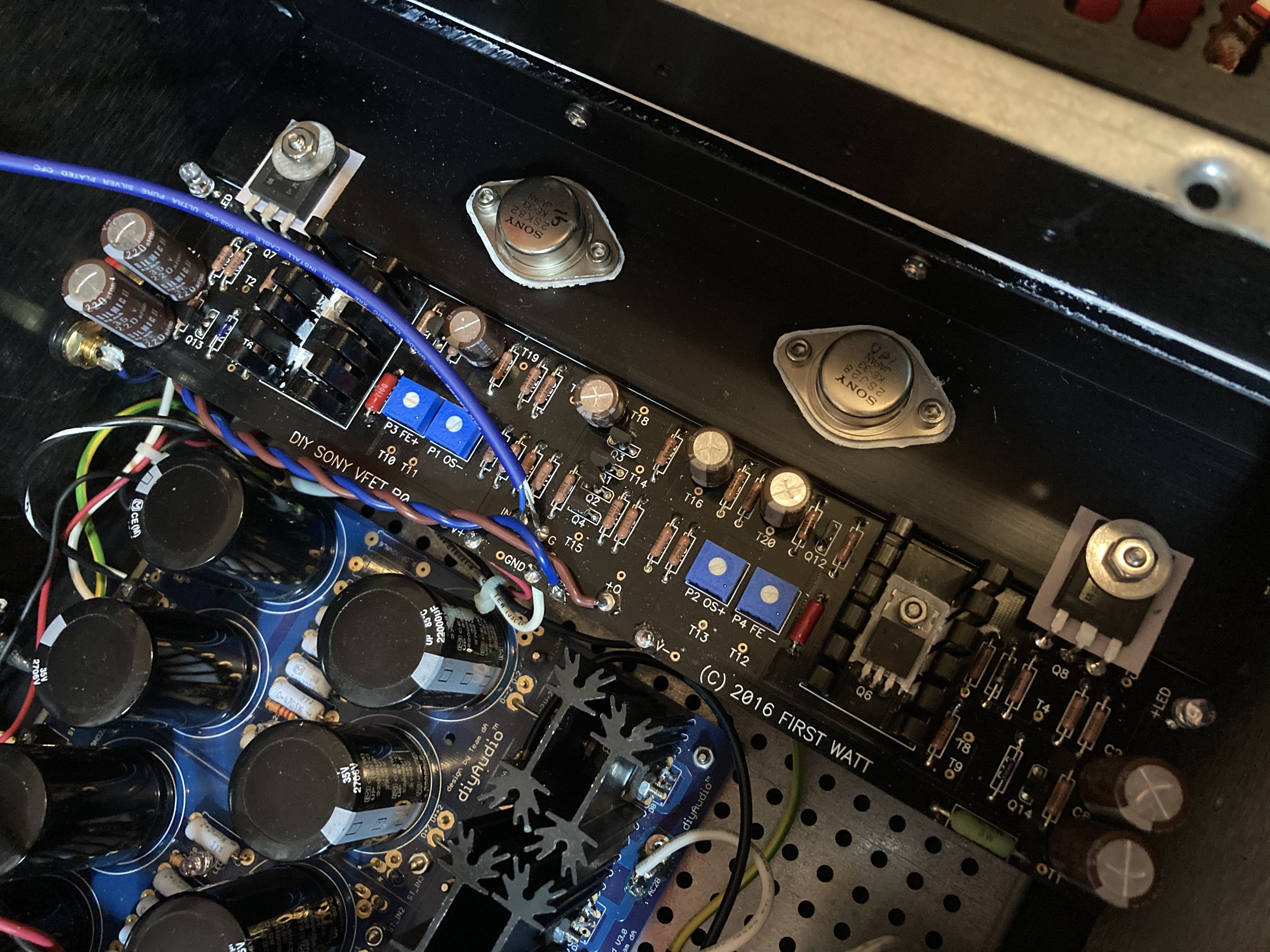
if these numbers (10 and 25mV) are in temp equilibrium, then you're done
chill, enjoy, go to surf
🙂
chill, enjoy, go to surf
🙂
- Home
- Amplifiers
- Pass Labs
- Sony vFET Illustrated build guide