Yes and it's not hard. Use the schematics as posted by Rodeodave above.
You can replace the voltage sent to the gate using a couple of 9V batteries in series
if you don't have an +/-19 V bipolar supply handy. (Also the voltage need not be
exact. Just in the neighbourhood will do.)
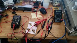
The main thing to remember is that you want to set the pot so the gate voltage
is at max magnitude. So for the 2sk82 you want the gate voltage to start at -19V
and then gradually adjust the pot to move the gate voltage towards the direction
of zero, while monitoring the voltage across the 1 ohm resistor (for current).
Stop when you have 0.5V across the 1 ohm resistor. The corresponding gate voltage
is the 'missing number' you want for that part.
Similar thing for the 2sj28, but with the initial gate voltage at 19V and slowly
decrease it towards zero until you get 0.5V across the 1 ohm resistor.
Hope this helps.
Dennis
You can replace the voltage sent to the gate using a couple of 9V batteries in series
if you don't have an +/-19 V bipolar supply handy. (Also the voltage need not be
exact. Just in the neighbourhood will do.)
The main thing to remember is that you want to set the pot so the gate voltage
is at max magnitude. So for the 2sk82 you want the gate voltage to start at -19V
and then gradually adjust the pot to move the gate voltage towards the direction
of zero, while monitoring the voltage across the 1 ohm resistor (for current).
Stop when you have 0.5V across the 1 ohm resistor. The corresponding gate voltage
is the 'missing number' you want for that part.
Similar thing for the 2sj28, but with the initial gate voltage at 19V and slowly
decrease it towards zero until you get 0.5V across the 1 ohm resistor.
Hope this helps.
Dennis
Thanks Dennis,
For heat sinking I was going to use the amps t bracket and heat sink. Amplifier board removed.
For heat sinking I was going to use the amps t bracket and heat sink. Amplifier board removed.
There's really not much to it. Watch the polarities, make sure the gate bias is there before the main supply voltage, and use light heatsinking.
Attachments

Ok. So apply the 19v to the gate. Then apply 19v to the second rail. With respective polarities.
I would like to build one. Who sells the amp in kit form? How do I get the v-fets? From Mr. Pass?
Build a time machine and go back to early 2017. 🙂 🙂 🙂 This was a one time project from years ago.
If you can find the Vfets, and watch out for counterfeit, the rest is simple and there are probably a few PCB left.
If you can find the Vfets, and watch out for counterfeit, the rest is simple and there are probably a few PCB left.
Hi,
I'm building a pair of bridged DIY Vfet amps, and finally managed to adjust one of them with the correct bias and offsets.
Before I move on to the second one, I just want to clarify the balanced input connections.
I'm connecting the XLR pin 2 directly to the input of one module, and XLR pin 3 to the input of the other module. I'm not 100% certain what to do with the signal ground (pin 1). The way I see it, I should connect it directly to the PSU ground, close to the star ground (I'm using 1 DIYAudio store universal PSU for both modules). Is that correct, or should it be connected elsewhere?
Thank you!
Paul
On all my constructions where I have balanced connections I never let the pin 1 to touch the PCB’s [emoji4] I just tie it to the chassis and I make sure that on the PCB there are resistive terminations to the input ground.
Wouldn't Pin 1 go to chassis only in amps with balanced input?
In my case, it would be a bridged amp, that's why I was thinking that signal ground should be connected to the ground shared by both Vfet modules.
In my case, it would be a bridged amp, that's why I was thinking that signal ground should be connected to the ground shared by both Vfet modules.
I see the bridged amp very similar to a balanced amp , the difference being the way feedback is applied. In your case the resistive inputs to the common ground will create two equal but out of phase signals for the two halves without the necessity to bring pin 1 to the boards. That's asking for trouble. But I think this is easy to verify yourself if one channel is ready and working. I would just test this to eliminate all the doubts
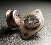
I tested all my VFETs.
They don’t seem marches closed enough.
2sk82: 8.4, 8.5, 8.9, 7.6.
2sj28: 9.6, 10.2, 10.1, 10.8, 11.1, 11.6.
They don’t seem marches closed enough.
2sk82: 8.4, 8.5, 8.9, 7.6.
2sj28: 9.6, 10.2, 10.1, 10.8, 11.1, 11.6.
You only need to match nn and pp pairs if you intend to run parallel output devices! For the standard diy Sony VFET amp from diyaudio you don't need that kind of matching. The Vgs numbers you pulled from your devices are handy for establishing the initial operating (biasing) conditions.
Notice the Vgs numbers on the schematic in the first post, they're quite dissimilar between n and p.
You have enough VFETs to build two stereo diy Sony VFET amps, and two 2sj28 to spare.
Notice the Vgs numbers on the schematic in the first post, they're quite dissimilar between n and p.
You have enough VFETs to build two stereo diy Sony VFET amps, and two 2sj28 to spare.
Hey Andrew,
Happy to see you've measured your parts. Were those at 0.5A current?
As Dave said, you're good to go. And the remaining two 2sj28 will be useful
should you want to build the upcoming vfet amp:
https://www.diyaudio.com/forums/pas...u-follower-amplifier-build-3.html#post6080459
Cheers,
Dennis
Happy to see you've measured your parts. Were those at 0.5A current?
As Dave said, you're good to go. And the remaining two 2sj28 will be useful
should you want to build the upcoming vfet amp:
https://www.diyaudio.com/forums/pas...u-follower-amplifier-build-3.html#post6080459
Cheers,
Dennis
Sony Vfet
I must add that the diy Sony Vfet is a really really good amp (just be carefull to use the right TL431 to avoid oscillations) and that I'm becomming very impatient/limit of running insane, to see Papa's new SIT version he's currently cooking with the same Vfets, fully disclosed!
I must add that the diy Sony Vfet is a really really good amp (just be carefull to use the right TL431 to avoid oscillations) and that I'm becomming very impatient/limit of running insane, to see Papa's new SIT version he's currently cooking with the same Vfets, fully disclosed!
- Home
- Amplifiers
- Pass Labs
- Sony vFET Illustrated build guide