Will it be first-come-first-served, or will there be a lottery to buy them, like getting into the Western States 100?
🙂
🙂
Hopefully kits will be limited to one per customer. That way we can keep the Greedy Boyz at bay.
Hopefully kits will be limited to one per customer. That way we can keep the Greedy Boyz at bay.
At the same time, I hope the PCBs can be purchased separately, for
those who already have the VFets. 🙂
Dennis
At the same time, I hope the PCBs can be purchased separately, for
those who already have the VFets. 🙂
Dennis
Hope as well 😉
Best regards
I'll certainly be interested in buying a few sets of front end pcbs if they are separate to the output stage.
I'll certainly be interested in buying a few sets of front end pcbs if they are separate to the output stage.
On Papa pcb's front end are not separate i guess they are all on ?
On Papa pcb's front end are not separate i guess they are all on ?
I was kind of hoping Papa might do it separate like BA3 front end.
I was kind of hoping Papa might do it separate like BA3 front end.
New front end pcb in DiyAudio Store ?
😀
Indeed, the front end should make a really nice preamp!
Tea bag's version has separate boards for those interested.
Tea bag's version has separate boards for those interested.
That magnetic shield band on the AS series is quite interesting and toroidy doesn't have that option. I remember seeing somewhere in the forum a member showing such a band to wrap around an existing transformer, but never found it again.
All the xformers shown in this thread should perform very well. Ordering close to home might be cheapest considering shipping costs. As you might notice Antek does not offer AS series lower voltage output xformers in sizes larger than 400VA. This does not bother me because I like to use 2 xformers in dual mono and stay below 500VA each with less load on bridges, contacts, ect. I also like to put large xformers in a separate PS enclosure away from the amp. Nevertheless, if you want a 500VA or larger with outer shield, email Antek and he will ship you a shield and heat transferring tape (mylar? without adhesive) along with the xformer to "wrap your own." I used some adhesive heat transfer tape on both ends to hold both ends. Be sure to wrap tightly. If you have DC in your AC lines, you might need to deal with that which is another thread.
Hi. Can someone explain to me how to measure the Sony VFET to match them?
NP mentionned in his article to match them for Vgs at 0.5A and 20V but no more details.
Is it that for example we connect the VFET to a 20V supply, limited in current at 1A for protection, and then we inscrease the Vgate until we meause 0.5A at the drain?
Let me know
Thanks
SB
NP mentionned in his article to match them for Vgs at 0.5A and 20V but no more details.
Is it that for example we connect the VFET to a 20V supply, limited in current at 1A for protection, and then we inscrease the Vgate until we meause 0.5A at the drain?
Let me know
Thanks
SB
Hi. Can someone explain to me how to measure the Sony VFET to match them?
NP mentionned in his article to match them for Vgs at 0.5A and 20V but no more details.
Is it that for example we connect the VFET to a 20V supply, limited in current at 1A for protection, and then we inscrease the Vgate until we meause 0.5A at the drain?
Let me know
Thanks
SB
Don't forget these are depletion mode devices.
Hi. Can someone explain to me how to measure the Sony VFET to match them?
NP mentionned in his article to match them for Vgs at 0.5A and 20V but no more details.
Is it that for example we connect the VFET to a 20V supply, limited in current at 1A for protection, and then we inscrease the Vgate until we meause 0.5A at the drain?
Let me know
Thanks
SB
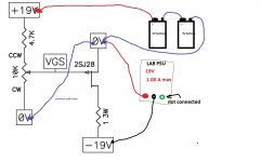
I had to measure some of my parts for the VFET V1 build. I just measured using a 19V laptop brick, 2 x 9V batteries, a potentiometer and a small value resistor.
Use the 9V batteries in series for the bias with the potentiometer to allow adjustment. Set bias to -15V before main power is connected and then just slowly turn on until 0.5A is detected via a small resistor.
I didn't use any current protection, however that could be useful to make sure that you don't fry any parts.
All my parts biased (in the amp) between -6V and -11.5V so the -15V start bias should be low enough to ensure no current flowing in the part at the start of testing.
The whole rig can be flipped to test the 2SJ28s pretty easily.
Hi. Can someone explain to me how to measure the Sony VFET to match them?
NP mentionned in his article to match them for Vgs at 0.5A and 20V but no more details.
Is it that for example we connect the VFET to a 20V supply, limited in current at 1A for protection, and then we inscrease the Vgate until we meause 0.5A at the drain?
Let me know
Thanks
SB
See http://www.diyaudio.com/forums/pass-labs/276711-sony-vfet-amplifier-part-2-a-11.html#post4392065
Hi Pico. What do you mean by that? SB
He means that if you don't apply bias before switch on then the part operates as a short.
I'd suggest -15V of bias relative to the source for a 2SK82 before voltage is applied across the part. -15V for the N-Channel parts (+15V for the 2SJ28) is sufficient to switch it off completely.
Hi. Can someone explain to me how to measure the Sony VFET to match them?
NP mentionned in his article to match them for Vgs at 0.5A and 20V but no more details.
Is it that for example we connect the VFET to a 20V supply, limited in current at 1A for protection, and then we inscrease the Vgate until we meause 0.5A at the drain?
Let me know
Thanks
SB
Hi Algar
Other schematic are in case if you don't have two lab psu's.
Attachments
- Home
- Amplifiers
- Pass Labs
- Sony vFET Amplifier Part 2