Anilva, what voltage did you use across them? It doesn't look like my distribution at 19v @ .5A per unit. The Vgs being a bit low.
I exactly followed NPs circuit and voltages. I used regulated +/- 19V DC supplies.
I have noticed that VGS can vary from 10 odd volts to 6 volts across different samples.
Cheers.
You always talk with K82 and J28... i have a bunch of K60 and J18 original Sony"s..... CAN A 3 parallel k60 and j18 overcome the the needs? It seem a monotonous thread only for K 82 aJ28 and nothing more.....obtain the un-obtainium?
Yes it can.
Yesterday I tested two paralleled 2SK60s, they have exactly the same curves as one 2SK82.
But as Zen Mod already said, since they are used here as followers, and at only 10 Watt ( 19V x 0.5A) per device, it can be a direct substitute.
Yesterday I tested two paralleled 2SK60s, they have exactly the same curves as one 2SK82.
But as Zen Mod already said, since they are used here as followers, and at only 10 Watt ( 19V x 0.5A) per device, it can be a direct substitute.
I have no luck again....😡
Bought 10 pieces (and get some discount) 2SK82 of the ALiExpress Eternal Hong
They are fakes, relabeled 2SK60's probably.... cause when I compare the curves of published 2SK60's they are exactly the same as in my picture (the blue line).
I measured all 10 V-FETs see pic.(Excel). There is one real 2SK82, V-FET number 7, strange enough...
Opened one up ( V-FET number 6), and there is one 3 mm die inside.😡
(BTW, This V-FET is still fully functional without the top.....🙂 )
Strange enough, Fast Freddy bought 4 pieces from this source that are different printed on top, so these are probably good ones.
I think Eternal Hong had a few good ones, and because demand is high, he re-printed some of his 2SK60's.... or bought more from a bad source...
He has sold to 14 buyers.

....hmm, well, it seems that i was the last one who got the real deal
from that infamous eternalHong-guy...

AliExpress lists all the buyers for an item.
i orderd mine on th 20th july, anilva, you orderd yours 3 days later and
got the fakes. but i don´t know where Fast freddy fits in the list, did you
order your´s on the 17th july ?
AFAIK the jA-33 types are from a different (earlier) production-batch than
the KD-33 or KE-33 ones with different dies in it, so maybe the pin orientation is not significant.
i just measured mine with a DMM and they´re ok
i hope to cobble something together to measure the Vgs till the weekend...

========

cheerio,
Mirko
Attachments

I believe that the SITs from Hong are real SITs but they are not 2SK82s. Most likely they are 2SK60s rank 2 that have been re-badged. The rank 2 would explain the different Vgs values.
As ilimzn points out in this forum thread - http://www.diyaudio.com/forums/showpost.php?p=3822318
I have a lot from Hong. I will put them on the curve tracer. My guess is that we will see lower gm than a real 2SK82.
As ilimzn points out in this forum thread - http://www.diyaudio.com/forums/showpost.php?p=3822318
I have a lot from Hong. I will put them on the curve tracer. My guess is that we will see lower gm than a real 2SK82.
Yes it can.
Yesterday I tested two paralleled 2SK60s, they have exactly the same curves as one 2SK82.
But as Zen Mod already said, since they are used here as followers, and at only 10 Watt ( 19V x 0.5A) per device, it can be a direct substitute.
Thanks for the info,,,now i can proceed....
I believe that the SITs from Hong are real SITs but they are not 2SK82s. Most likely they are 2SK60s rank 2 that have been re-badged. The rank 2 would explain the different Vgs values.
As ilimzn points out in this forum thread - diyAudio - View Single Post - Sony SITs - 2SK82 E Rank With 2SJ28 F Rank
I have a lot from Hong. I will put them on the curve tracer. My guess is that we will see lower gm than a real 2SK82.
i just read that complete thread... now i have a headache...😕

but ilimzn surely knows his VFet´s
and sometimes you don´t get answers, only more questions
me thinks the only safe way to determine, if you have k60 or k82 is to
measure the transconductance
k60 should have a GM of 250mS and K82 should have 500mS
(although i don´t have clue how to measure the GM...)

=========
cheerio
Mirko
Attachments
Ah, Eternal Hong has stopped selling all his relabeled VFETs.
I've sent my 10 pieces back, minus the one I opened up and minus the good 2SK82 which matched perfectly with one of the Acronmans.
I've sent my 10 pieces back, minus the one I opened up and minus the good 2SK82 which matched perfectly with one of the Acronmans.
Anyone with at least two unmatched VFETs of either polarity will be able to
build something of interest, no problem. The only limitation will be power.
Anyways, be patient and no one will go hungry.
😎
build something of interest, no problem. The only limitation will be power.
Anyways, be patient and no one will go hungry.
😎
 Teaser ???
"Eternal Hungry"😀
I have build the CSX1 and it's my number one amp I listen to.
But a bit more gain and power is what I'm looking for.
Will there be a Common Source 'Turbo' 'ish article?
I have bought an extra pair of 2SJ28's when I heard Mr Pass talk of this. I did not want to wait for the plans and schematic and then be caught with none to buy because someone speculates and buys them all from Acromans much as the Sony Vfet2 2Sk82 Vfets. You better get them now because when old stock is gone they are gone for good. Exorbitant prices and fakes is what you will find later. I have most of the parts to build the Sony Vfet 1 but decided to wait to see what comes from the mind of the master. I would like to see a SE one stage amplification circuit much like the SIT 2 for these Vfets if possible. The iron amp is one but with output transformers.
I am patiently waiting.
I am patiently waiting.
Anyone with at least two unmatched VFETs of either polarity will be able to
build something of interest, no problem. The only limitation will be power.
Anyways, be patient and no one will go hungry.
😎
Yes,yes,yes ....
I be patient .... 😉
😀
🙄....
Anyone with at least two unmatched VFETs of either polarity will be able to
build something of interest, no problem. The only limitation will be power.
Anyways, be patient and no one will go hungry.
😎
Hmm, yeah, only 2 VFETs calls for single ended, but it should be something
different than Michael R´s l'Amp with it´s minimalistic approach in it´s
4 variants
i´m now at the planning-stage of building a choke-loaded l'Amp,
and now i guess, i should wait just a little more.... 😀


Anyways, be patient and no one will go hungry.
😎
Ah .. manna from heaven ...
If only 2SK82 and 2SJ28 were loaves and fishes ...
After water into wine, maybe IRF240 into Pass SIT?? 😀
Many thanks (again) Mr Pass
Last edited:
Like in the case of WalterW, I too got 4 pieces of 2SK82 from EternalHong on Aliexpress. The printing is distinctly different from the ones I got from Singapore and is also printed upside down from a pin orientation perspective. I am fairly certain that they are not the genuine Sony VFETs.
Cheers.
The seller offered to refund me the money. Aliexpress's purchase protection works.
Cheers.
Anyone with at least two unmatched VFETs of either polarity will be able to
build something of interest, no problem. The only limitation will be power.
Anyways, be patient and no one will go hungry.
😎
Like many of you, I asked: What can this proposed build by Mr. Pass be? I have no doubt that we'll find out in good time. In the interim, I scribbled a schematic to attempt and tackle this problem at hand.
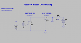
The attached is a schematic of a cascoded amp. The cascoding device is a depletion-mode type like 2SK82 or SJDP120R082. Please note the following:
1. The term pseudo-cascode means that Vds of NMOS [or R100] is not a constant voltage during operation. As its dynamic impedance changes [say decreases] the source voltage of the VFET also decreases so as to accommodate the increased current enabled by NMOS or R100.
2. The depletion-mode device [2SK82] operates as a common gate power amplifier.
3. The VFET properties of 2SK82 are preserved. For any value of a drain current which is common to both devices, this depletion-mode device ascribes or associates a certain Vgs to it which is solely dictated by its Volt-Amp characteristic. The voltages at the terminals of VFET float [as a function of Idss] like those of any other device used to cascode others.
4. There is also a hypothetical schematic which complements the attached one. I'll show both schematics in two hypothetical applications in the next post.
Attachments
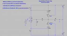
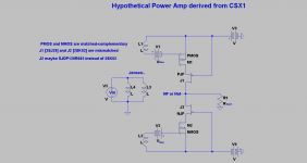
Schematics of 2 hypothetical apps are attached; namely a modified diyF5 and a modified diyCSX1. A common approach is used in both.
1. The NMOS and PMOS in diyF5 and in diyCSX1 must be matched-complementary. The N and P VFETs need not be matched. This approach attempts to tackle the problem at hand.
2. What gives? Vds of NMOS and PMOS are not equal; reflecting the mismatch of Vgs of VFETs at any constant Idss.
3. What if I introduce a gross mismatch; like using 2SJ28 and SemiSouth's R085 [instead of 2SK82] depletion-mode devices? Concept suggests that it'll work; because the principal operational players are the N and PMOS like in any cascode system.
4. The output impedance of the modified CSX1 is higher than the parent's 4 Ohms?; because the dynamic impedance of the Mosfets are in series with that of the depletion-mode devices.
Attachments
And here's the good news.
I have tested the single-pair version of the amplifier with good results.
It has a little more distortion and a little less power, but not by much. It
delivers 20 watts into 8 and 30 watts into 4 ohms. I am going with the
feedback version, but you can have the no-feedback version by changing
a couple resistors.
This will double the number of channels that can be built, and no matching
of the parts is required. I am planning to supply 400 pair of the devices
to the DIYAudio store. TO-247 IR parts will be used for the regulators.
I have drawn up a T-bar mounting bracket to fit the 300 mm deep heat
sink (also will fit the 400 mm) chassis offered in the DIYAudio store and
will be doing a pc board to fit it.
Presumably those who plan to use matched dual pairs can go with Tea
Bag's boards or they can bolt the extra devices in parallel. The performance
should be about the same either way.
On my end this will proceed over the next few weeks. Those with only one
polarity of VFETs will be addressed in a separate design after that.
😎
- Home
- Amplifiers
- Pass Labs
- Sony vFET Amplifier Part 2