The principle is pretty straightforward: I haven't got the circuit in front of me but here goes...
take one self oscillating power stage that delivers a squarewave to the chopper transformer (we always called them chopper transformers as a generic name in any type of PSU) and regulate its secondary output indirectly by sensing the voltage on a secondary winding. This 'feedback' then controls the main supply voltage applied to said convertor through a series regulator as a means of regulating the PSU. The series regulator feeding the oscillating stage is also a bit unique in that it is a mix between a conventional series pass regulator and a switching stage.
The problem is that it is all far to dependent on the semiconductor device characteristics for reliable operation.
Well, that's more or less clear. But with my scope I can't see any square wave given the current state. Oscillating power stage - yes, but which stage in particular circuit? We should see the cap in the base discharging to some load in collector...
There is so much HF energy flying around that it might not be easy for a scope to trigger and latch on to display clearly.
The four power transistors in the output stage get their drive directly from the chopper transformer via small auxiliary windings. That part is all self oscillating... it runs at full tilt all the time. The only way that any control is exercised is by sensing what is going on via another winding and using that to control the series regulator supplying it.
Modern SMPS regulate by varying the duty cycle of the switching transistor. This doesn't, it runs flat out all the time with only the supply voltage as a means of controlling its output.
There is so much HF energy flying around that it might not be easy for a scope to trigger and latch on to display clearly.
Modern SMPS regulate by varying the duty cycle of the switching transistor. This doesn't, it runs flat out all the time with only the supply voltage as a means of controlling its output.
Yes, that was a confusion not seeing any pulse width modulation there, having the voltage regulated by sort of classic regulator.
As for the oscillation, my gut feeling is that Q607 shall be an oscillator, discharging to RED 20T winding and driving bases of invertor transistors...
Q607/608 have the look of an old fashioned unijuction type relaxation oscillator but I'm not sure that is how they behave tbh. You can make a UJT from discrete transistors.
Unijunction Transistor and UJT Relaxation Oscillator
Unijunction Transistor and UJT Relaxation Oscillator
Q607/608 have the look of an old fashioned unijuction type relaxation oscillator but I'm not sure that is how they behave tbh. You can make a UJT from discrete transistors.
Unijunction Transistor and UJT Relaxation Oscillator
well, at least schematically looks very similar... thanks
Update:
1. OK, it works with MJE15032G (hFe>100 @100mA)
2. Output voltage (no load) is +/-80V
3. Safety bulb still in place (75W) giving 210V at PSU input with no load and just 140V with 50W load bulb at the output.
4. Will try tomorrow getting 100W bulb and try.
5. Possibly have to consider transformer secondary rewinding to get lower output.
The fact it 'works' with your MJE's fitted is proof again of how fussy this design really was. I'm not sure rewinding the transformer is a great idea tbh. There is no way back from that and its more of a 'fiddle fix' anyway.
Yes, on second thought I have denied this idea. Moreover the transformers in 110V and 220V are the same (given the same amount of winding turns - indicated right on the scheme). So basically for today I have two issues:
1. blowing parts if connected without "safety bulb"
2. output voltage is double to the normal.
1. blowing parts if connected without "safety bulb"
2. output voltage is double to the normal.
I would always try and have a small load present on the output, perhaps a 40 watt bulb. Strange things might happen with no load.
The output voltage could also be wrong because it might be running at an incorrect frequency or running at some harmonic of where of should be (fussy on parts again).
The output voltage could also be wrong because it might be running at an incorrect frequency or running at some harmonic of where of should be (fussy on parts again).
If someone still reading...
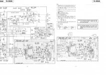
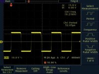
I did the scoping on secondary winding, got ideal square wave with 52us period (circa 19kHz) and about 170V amplitude. Seems it's pretty close to the numbers on the scheme = 180V amplitude and 42us period. But how they get +/-45 after rectification and caps from square wave 180V? Total misunderstanding... Attaching portion of scheme and the scope dump.
I did the scoping on secondary winding, got ideal square wave with 52us period (circa 19kHz) and about 170V amplitude. Seems it's pretty close to the numbers on the scheme = 180V amplitude and 42us period. But how they get +/-45 after rectification and caps from square wave 180V? Total misunderstanding... Attaching portion of scheme and the scope dump.
Attachments
The numbers in the manual don't add up at face value. A 50 or 90 volt peak input to the bridge has to generate 50 or 90 volts DC across each reservoir cap.
What DC voltage have you got ?
What DC voltage have you got ?
And that's what basic theory would suggest. I can't make sense of the numbers in the manual.
Does the voltage fall considerable under light loading ?
I also see this version has a switched secondary. Is it on the high or low setting at the moment.
I've no answers I'm afraid.
Does the voltage fall considerable under light loading ?
I also see this version has a switched secondary. Is it on the high or low setting at the moment.
I've no answers I'm afraid.
No, no voltage falling with bulb load. Switching secondary is to feed Class A operation with very high quiescent current.
I have to grab operating 220v unit then, just to check all voltages myself... as well I will revert to other amp unmodified 110v psu just to check what's on secondary winding.
Thank you so much for your help.
I have to grab operating 220v unit then, just to check all voltages myself... as well I will revert to other amp unmodified 110v psu just to check what's on secondary winding.
Thank you so much for your help.
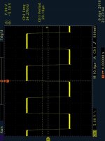
Well, just checked 110v unit. Secondary winding amplitude is almost the same - about 180V, that's true with schematic. But look at the frequency - it's almost 33kHz giving just 30us period. Higher frequency - higher voltage drop after rectification?
Attachments
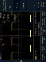
Does this 110v unit give the correct DC rail voltages ?
If there were a drop in the rectified output because of the frequency going up then the 'lost voltage' has to go somewhere. If it were across the diodes then they would fry at the currents involved.
If there were a drop in the rectified output because of the frequency going up then the 'lost voltage' has to go somewhere. If it were across the diodes then they would fry at the currents involved.
yes, it does produce absolutely correct DC rails voltage. I wouldn't assume such drop is possible over diodes - seems it's normal silicon diodes with maximum 0.7v drop. Maybe its not "ideal" square wave giving lower effective voltage... but the scope is pretty fine.
- Home
- Amplifiers
- Solid State
- Sony TA-F6B PSU repair