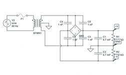
A typical power supply would be like this. The four small caps are optional and are "snubbers" to prevent commutation noise from the rectifiers as they come in and out of conduction. The resistors aren't needed... your amp is the load.
The transformer would need to be no higher than 35-0-35 vac which would give around -/+50 volts DC when rectified and smoothed.
The transformer would need to be no higher than 35-0-35 vac which would give around -/+50 volts DC when rectified and smoothed.
Attachments
ta-n86 PSU 110-220v switch
Hi Folks,
being read this thread with pleasure. Currently working on idea to switch several tan-86s to 220v with its PLPS, thankfully PCB and transformer are the same and almost 60% parts are the same. And tan-86 PLPS is identical to that used in TA-F6.
I have finished changing all parts to the values shown for 220v version, yet BJTs are modern MJE13007 and similar.
Issue no is that there's no oscillation and invertor does not work. Starting circuit of Q607-Q608 showing zeroes or <1v at all their pins, while voltage reg output (L604) does producing 250V stable voltage, as prescribed.
Any ideas how to make it oscillating? My knowledge limited to modern PLPS driven by special ocillating chip and power mosfet. But I am failed to understand this old-fashioned design of BJT oscillating schematic.
PLPS schematic is attached.
Attachments
Hard to say whats going on here. Did they all work correctly on 120vac ?
These self oscillating PSU's were very critical on the semiconductor types used if I recall correctly.
These self oscillating PSU's were very critical on the semiconductor types used if I recall correctly.
Hard to say whats going on here. Did they all work correctly on 120vac ?
These self oscillating PSU's were very critical on the semiconductor types used if I recall correctly.
Sure they did, everything was absolutely fine.
To the overall condition now I want to add that after modifications for 220v input, I have fully operational voltage regilaton section with 250v outpit, adjustable with pot, but the voltage drop at Vce on Q604 is not correct - should be 140v but I have 320, so that means Q604 is totally closed.
Have an idea just to revert everything back except of voltage regulator section adjusted for initial output of 140v to feed the invertor and starting circuit. The only concern is heat dissipation and lowered overall efficiency.
Nevertheless, still want to understand the principle of oscillating in this PLPS original design and function of "starting section". Still wondering why Q607 and 608 are zeroed at their pins. Double and triple checked them and nearby diodes...
Last edited:
Q604 voltage doesn't sound correct. If you have 320v across it then it suggests its not turned on at all... however it must be functioning to be able to control the 250 volt, and you say the 250v is fully adjustable. Perhaps that section of the circuit is actually oscillating/switching and the resulting on/off voltage on Q604 is confusing a DVM.
You have to be very careful if you scope this... make sure you feed the PSU from an isolation transformer first.
The start up of all these types of supply is a bit weird. I think Q607/8 provide (initially at least) nothing more than a change in flux in the auxiliary windings on the chopper transformer as the main HT appears, and that is enough to 'kick' the thing into life.
I also have 4v on Q604 base... with all correct voltages in error amp (Q605/606) and 6.4v Vce. So feeding Q604 base form Q606 collector can't give anything else then 4v, so Q604 is closed. Maybe your assumption on semiconductors type is doing the trick - can't find anything feasible about 2sc1810 though - but if its true silicon it should open as usual with 0.6v Vbe. By the way C601 and C603 still not soldered in, but to my opinion this is irrelevant.
As for the safety - yes, will try scoping this tonight with 1x100 probe... or even consider the probe with isolation transformer... thanks for the idea.
As for the safety - yes, will try scoping this tonight with 1x100 probe... or even consider the probe with isolation transformer... thanks for the idea.
If Q604 were 'closed' (closed = turned on) then the collector would be down at zero volts (same as emitter).
If you have 4 volts on Q604 base (and so 4 volts across Q604 B-E) then something is amiss in the readings. If you can adjust the regulator with the preset then Q604 has to be functioning. At this point I'd suggest the DVM readings are suspect possibly due to the PSU being in some oscillating state.
If you have 4 volts on Q604 base (and so 4 volts across Q604 B-E) then something is amiss in the readings. If you can adjust the regulator with the preset then Q604 has to be functioning. At this point I'd suggest the DVM readings are suspect possibly due to the PSU being in some oscillating state.
If Q604 were 'closed' (closed = turned on) then the collector would be down at zero volts (same as emitter).
yes, with 4V base-emitter it's turned off completely, pls excuse my terminology. The lowest Vbe I can get rotating the pot is 1.7V which still seems high.
Two interesting things are now discovered on schematics: PLPS DC input from the main board (after rectifier and cap) is shown as 280v (right upper corner), but with 220V input it should be not less then 310 (220*√2). Secondly - there's some switching does exist on voltage reg output (shown as 300v amplitude 42us) - is it an oscillation, or just switching load (invertor) effect ?
Attachments
🙂 4 volts across B-E (with the base positive with respect to emitter) would normally mean the base emitter junction is open circuit but it can't be because the regulator is working.
When you feed a forward current into the B-E junction the transistor will conduct from C to E. Feed enough current in and the transistor would become totally 'closed' or conducting between C and E.
You would need to look at the key in the service manual to see what mains voltage the double brackets ((280v)) refer to.
The base emitter voltage drop will always level out at around 0.7 volts or so but only when reading static values. If its dynamic (oscillating) then although it still levels out at 0.7v in the forward direction, the oscillating nature means a DVM can give totally incorrect readings.
The TA-N86B circuit is a bit more complicated than the one in the TA-F6B. The pre-regulator is a 'hybrid' in that it starts in linear mode and then uses the oscillation from the push-pull converter to go into switchmode operation. Conversion to 230V operatin should best be done by leaving the push-pull converter as it is, and just changing the pre-regulator. The parts in it should be capable to withstand operation at the same pre-regulator output voltage. The pre-regulator should not be much less efficient under these conditions except in start mode, but that should only last a few seconds.
The TA-N86B circuit is a bit more complicated than the one in the TA-F6B. The pre-regulator is a 'hybrid' in that it starts in linear mode and then uses the oscillation from the push-pull converter to go into switchmode operation. Conversion to 230V operatin should best be done by leaving the push-pull converter as it is, and just changing the pre-regulator. The parts in it should be capable to withstand operation at the same pre-regulator output voltage. The pre-regulator should not be much less efficient under these conditions except in start mode, but that should only last a few seconds.
yes, I had the same idea. So you mean I just change parts in voltage reg (Q601-604 and Q613) and leave everything else intact? And how does voltage reg goes into switching mode?
Last edited:
OK, just went through additional measurements. Some previous info I gave was incorrect.
1. Q604 Vce drop is not 320, but 250, same as voltage reg output.
2. Q604 base is fluctuating from zero to 0.1v, and my digital multimeter show jumps in 1-2 sec. Have to check with the scope...
3. Put back all four 2sc1986 BJTs to invertor, double checked them before installation all tested fine. Got shortened voltage reg output and radiator heating. Protective 100w bulb at the AC input gets some minor lighting (1/3 power roughly ).
4. then I cut the link to the convertor (+V regulated rail) and everything reverted to the state as before. So I suppose some sc1986 got blown.
Last edited:
Hmmm... can't really advise you much on this I'm afraid. They are a very difficult PSU to work on and very component critical.
And be careful where you connect that scope ground lead. The primary side is all live remember.
And be careful where you connect that scope ground lead. The primary side is all live remember.
Hmmm... can't really advise you much on this I'm afraid. They are a very difficult PSU to work on and very component critical.
And be careful where you connect that scope ground lead. The primary side is all live remember.
Thanks anyway. I have ordered already all original BJTs from ebay - will try to put them all in place, no substitutions, and then I see what happens.
 for you.
Hi Everyone!
Short update:
1. Have installed four "old" BJTs for invertor (2SC1986).
2. PSU starts oscillating and produce stable output.
3. However, it only works with "safety" 75W bulb in series with AC mains.
4. Because of the bulb PSU input voltage drops down to 180V giving the PSU stable output of circa 60V.
5. Voltage reg output (L604) / Invertor input does producing circa the same voltage - 175V. Other voltages are total mess as well (obvious).
6. Tried to remove the bulb and run the whole thing directly from full-scale AC. Got blown "soft start" resistors at the main board ( 2x 2.2 ohm 5w), first two BJTs in invertor (Q609/10) and Q613/601 in voltage reg.
7. All blown BJTs replaced with BUT11AI (all four replaced in invertor for sure). Voltage reg is OK, but no oscillation, invertor does not start.
8. Patiently waiting 2sc2023 - two weeks or so for delivery...
Ideas? Why other BJTs can't oscillate? Low Hfe? "older" 1986s were with beta of 35-40, modern MJEs and BUTs are 22-23...
Last edited:
Ideas? Why other BJTs can't oscillate? Low Hfe? "older" 1986s were with beta of 35-40, modern MJEs and BUTs are 22-23...
That is the big question. It seems these PSU's are very dependent on semiconductor type. I think the honest answer has to be that they are not the best design... but it was all new thinking back then, these were a first.
That is the big question. It seems these PSU's are very dependent on semiconductor type. I think the honest answer has to be that they are not the best design... but it was all new thinking back then, these were a first.
True. Nevertheless, it is an interesting challenge - in order to understand such behavior we need to understand the basic principle.
- Home
- Amplifiers
- Solid State
- Sony TA-F6B PSU repair