The 2SC2240 is much higher gain so you could try that for Q405 but try dabbing a reistor first... easier and quicker.
Don't loose sight of the fact that the relay and those transistors are just a basic configuration... it has to work.
You have the -44 volts supply.
We know the relay clicks when you short out the driver transistor.
All you need is the base bias current to turn those transistors on.
Q406 has proved by measurement to be faulty (open).
Its odds on you just need higher gain devices... or we can fiddle it with R416, the 150k 🙂
Don't look any deeper than this, it has to work.
I soldered a 47k across R416, to no avail.
My voltages around the transistors are:
Q406:
E -42
C 0
B -41
Q405
E -41
C 0
B -42,6 (-44,9 without the 47k across the 150k)
I'll proceed to check the diodes D409 and D410.
My voltages around the transistors are:
Q406:
E -42
C 0
B -41
Q405
E -41
C 0
B -42,6 (-44,9 without the 47k across the 150k)
I'll proceed to check the diodes D409 and D410.
I put the good 2SC1364 back at position Q406 and put a 2SC2240 at position Q405. no changes, no relay function.
This is all exceedingly odd but I'm not going to deviate from the theory of how it should work 🙂
That 220uF cap on the base of Q405. Is that OK? and not suffered due to that negative base voltage we had earlier. Just a thought.
Lets do this one step at a time.
1/ Fit only Q406 and remove Q405.
2/ Connect something like a 3k3 or a 4k7 between the base of Q406 and ground. That will supply about 15 milliamps base current and should switch Q406 correctly. Just dab the resistor on the board. That has to work.
The resistor will dissipate about 0.5 watt so will be finger hot but its just a test.
Feeding time 🙂
I replaced all the caps earlier this morning, so this should be good.
OK I'll remove Q405 and connect a resistor between the base of Q406 and ground. I need to find ground in that circuit....
have a nice lunch!
OK I'll remove Q405 and connect a resistor between the base of Q406 and ground. I need to find ground in that circuit....
have a nice lunch!
This is all exceedingly odd but I'm not going to deviate from the theory of how it should work 🙂
1/ Fit only Q406 and remove Q405.
2/ Connect something like a 3k3 or a 4k7 between the base of Q406 and ground. That will supply about 15 milliamps base current and should switch Q406 correctly. Just dab the resistor on the board. That has to work.
The resistor will dissipate about 0.5 watt so will be finger hot but its just a test.
Feeding time 🙂
It works! I didn't leave it on so didn't check the temp of the resistor.
dog-and-cat-walk-time!
Eschenborn
Excellent. So that shows Q406 and the relay continuity and so on is OK.
So now we fit Q405... and... I'm thinking aloud now... can you check that the two diodes that generate the bias voltage (that's D605 and D606) and also the two caps that are across those diodes are OK. They would have to be checked out of circuit. The caps are just for suppression and could just be lifted as a test. The diodes would need a very careful check for any leakage. Maybe even replacement to be certain. 1N4007 types would be OK.
If any of those were leaky by just the right amount it could give this exact fault you have... a chance in a million but we have to consider it.
Back to Q405 if the above is OK. We refit it and without soldering the base into circuit (and having removed the test resistor from earlier) we now dab a much higher value resistor from the base of Q405 to ground. Lets say 220k as a minimum, you can go to 470k, 680k, even 1meg.
The relay should operate because you have a true high gain Darlington configuration in those transistors. It may be so sensitive that even you just touching the floating base lead causes the relay to buzz rapidly as it picks up stray 50Hz mains from you.
the cat insists on walking with the dog and me (and then ventures into a garden and doesn not come back e.g... so it can take ages. but he insists, as only cats can insist).
ok I will do as you say tomorrow. now I am too tired. thanks for walking ME so far! that's really generous of you.
good night!
ok I will do as you say tomorrow. now I am too tired. thanks for walking ME so far! that's really generous of you.
good night!
It's an interesting issue and as we haven't really nailed it yet (and I'm hoping those diodes/caps might just... you know) then we have to build that part of the circuit up in stages and check it behaves correctly each step of the way.
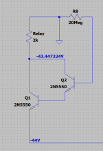
This is the configuration, just the supply, the transistors and a really high value resistor as a bias source.
There is so much current gain from a Darlington pair (the individual gains of each transistor multiplied together) that even a 20 meg (in the simulation) provides enough current to fully turn the relay driver on.
That's just 2uA base current in that resistor.
Attachments
Good morning!
I did as you advised and the relay opened (dabbed a 470k between base of Q405 and ground).
I also measured D605-606, they measured ok (both leads out of circuit). But since I had already unmounted the PS board, I decided to change the old diodes (10E2) against new ones with a slightly lower amperage rating (UF4006, which I had at hand). I hope that will be ok.
(The PS board is soldered on top of the pins of the big PS double cap can. This is not very practical. In order to put in new PS filter caps, one would have to change the layout, as is shown in this thread Sony TA-3650 restoration | Audiokarma Home Audio Stereo Discussion Forums)
How to proceed from here? There is still R412 lifted with one lead, and there is the 47K in parallel with R416 at the moment.
Should I try to see if there is output from the power amp with the relay engaged? I admit that I am curious. But that may be a very amateurish haste.
I will need to do a couple of work-related things today (a lot actually, as I lost the whole of day yesterday to SONY). Thanks for your generous help, Mooly. I totally get that you also have some other things to do 🙂 It's a wonderful experience to receive your assistance, but it nearly becomes to much to ask for. Please put it on the last place on the to-do-list 🙂
Eschenborn
The voltages are:
V1: 23.4 V
V2: -16.36 V
V3: -32,20 V
V1 supply from the transformer (should have 30V AC) with 2 diodes full wave rectifier so that 23.4V voltage is a little bit low, but V2, V3 seems normal.
I suspect cap C407 not right, I suggest try this, remove R412, R415 first to isolate the relay drive circuit alone, exchange C407 with C406 temporarily for testing, for the transistor 2sc2240 as Q405 and 2sc1364 as Q406, please also measure the V4 voltage.
Attachments
Hi patrick101, thanks! Interesting!
C407 should be ok, as is new. I exchanged all the caps yesterday with new ones to spec.
At the moment there is 2SC2240 as Q405 and 2SC1364 as Q406 (as you suggest, albeit in the configuration with the base of Q405 pinned to ground via a 470k resistor).
I didn't touch R415 so far. I'd suggest waiting for Mooly's comments and proceed from there (otherwise the stuff I need to test becomes contradictory in the circuit).
Thanks a lot!
V1 supply from the transformer (should have 30V AC) with 2 diodes full wave rectifier so that 23.4V voltage is a little bit low, but V2, V3 seems normal.
I suspect cap C407 not right, I suggest try this, remove R412, R415 first to isolate the relay drive circuit alone, exchange C407 with C406 temporarily for testing, for the transistor 2sc2240 as Q405 and 2sc1364 as Q406, please also measure the V4 voltage.
I measured the voltages around Q406 and Q405 yesterday, as in post #83. Sony TA-3650 power rail resistors burn
so V4 should be 1.6V (with the 47k across the 150k at position R416.
I measured the voltages around Q406 and Q405 yesterday, as in post #83.
so V4 should be 1.6V (with the 47k across the 150k at position R416.
My voltages around the transistors are:
Q405
E -41
C 0
B -42,6 (-44,9 without the 47k across the 150k)
According to your Q405 voltage reading, in normal(no 47K connected) the base at -44.9V, so that it is same as the negative supply rail voltage and the Q405(Q406) will not turn on.
If the caps are new then you just remove R412 and R415 and do not connect the extra 47K to 150K and power on the amp to check the result.
Please measure the voltage V4 according to the diagram "not measure between the ground".
Last edited:
thanks.
the relay does neither turn on with the 47k across the 150k.
how does the neg supply voltage get there? on the base of Q405?
I'll test as you say. give me some minutes.
the relay does neither turn on with the 47k across the 150k.
how does the neg supply voltage get there? on the base of Q405?
I'll test as you say. give me some minutes.
thanks.
the relay does neither turn on with the 47k across the 150k.
how does the neg supply voltage get there? on the base of Q405?
I'll test as you say. give me some minutes.
Do you remove R415 when test
NO.
the negative supply voltage I measure is -42V. (It's a bit lower than in the schematics).
so if I don't tag the 47k across R416 the base of Q405 gets a higher negative voltage than the supply V is (actually 2,9V higher).
so maybe here is a track here?
the negative supply voltage I measure is -42V. (It's a bit lower than in the schematics).
so if I don't tag the 47k across R416 the base of Q405 gets a higher negative voltage than the supply V is (actually 2,9V higher).
so maybe here is a track here?
- Home
- Amplifiers
- Solid State
- Sony TA-3650 power rail resistors burn