PS the relay does NOT switch in this constellation (which is the one from right of the beginning, only that I substituted a 2SC2240 for Q405).
OK so now something interesting happened when I connected the scope: R421 (power rail resistor) burned. I hope I am not making things worse...
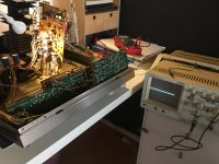
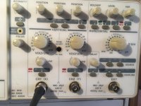
I am not really a pro with the scope; my son (who does a degree on informatics & engineering) gave it to me for christmas, and I used it only once to troubleshoot a Kenwood KR-100 receiver (with success, hooray).
I connected the scope as I did with the DMM, black lead to rail (the black lead is a groundig clip actually). should have waited for exact directions... but maybe this is a helpful glitch?
feeding time here as well.. and then a walk with the cat.
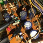
some pics attached to give the whole process more materiality...
I am not really a pro with the scope; my son (who does a degree on informatics & engineering) gave it to me for christmas, and I used it only once to troubleshoot a Kenwood KR-100 receiver (with success, hooray).
I connected the scope as I did with the DMM, black lead to rail (the black lead is a groundig clip actually). should have waited for exact directions... but maybe this is a helpful glitch?
feeding time here as well.. and then a walk with the cat.
some pics attached to give the whole process more materiality...
Attachments
😱
It has burned because (I would guess) that you used the -44v rail as ground for the scope... and the scope has a mains ground connection as well as the amp... and so you shorted the -44v rail out via the scope leads and mains ground.
Is that what happened? If so then probably nothing worse than a burned resistor.
We must use chassis ground for the scope in these instances.
PS the relay does NOT switch in this constellation (which is the one from right of the beginning, only that I substituted a 2SC2240 for Q405).
So this is where it gets really really interesting... but first you have to get it back to where it was 🙂
We know the relay should switch with just a couple of uA of base current... and that apparently is not happening.
So you measured +10v from the -44v rail. Its about in the right ball park but only just. This is where the scope comes in.
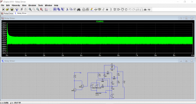
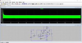
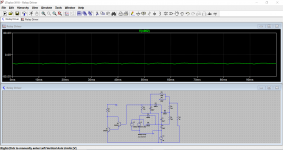
What do you see when putting the scope on the top of R416. Use DC coupling on the scope. It will be a negative voltage and should be around -34 volts but what does it look like? How much ripple is there.
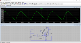
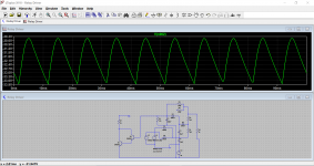
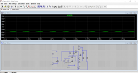
This is what the simulation looks like. The second image is with the timebase opened out. Notice the ripple and also notice how low the negative peaks are.
Are yours anything like this or is yours going much much negative?
Attachments
😱
It has burned because (I would guess) that you used the -44v rail as ground for the scope... and the scope has a mains ground connection as well as the amp... and so you shorted the -44v rail out via the scope leads and mains ground.
Is that what happened? If so then probably nothing worse than a burned resistor.
We must use chassis ground for the scope in these instances.
ok good. I think that's what's happenend. So I am going to solder in a new resistor and then look at the ripple.
so now if I only could read – and adjust well – the scope.
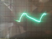
I have it on the 5V setting vertically and on the 5ms setting horizontally. I'd say it shows 2 ms peak-to peak, and 40% (it's a percent scale vertically) of the 5V range, so about 2V ripple.
When I read your simulation well, it's 8ms peak-to-peak, and about 3.4V ripple.
I'll send some pics in case I totally confused the readings, I'll attach them to the next post.
Last edited:
so here are some pics of the scope reading. I am afraid the scope is as vintage as the amps I am dabbling with.
the vertical scale is in %, one square is 20. The horizontal scale has ten squares.
the vertical scale is in %, one square is 20. The horizontal scale has ten squares.
Attachments
Your amp relay circuit behave is quite strange, if there is high ripple in V3 to ground, maybe the +V supply problem, please check D605 and D606 in the power supply board.
Your amp relay circuit behave is quite strange, if there is high ripple in V3 to ground, maybe the +V supply problem, please check D605 and D606 in the power supply board.
hi patrick, thanks!
as I wrote in post #93, I already substituted D605 and 606 with new ones.
as I wrote in post #93, I already substituted D605 and 606 with new ones.
Ok, after replaced new diodes, caps and even transistors, still not ok, maybe not only component problem, please try scop the relay circuit form point to point try to find out something wrong.
so here are some pics of the scope reading. I am afraid the scope is as vintage as the amps I am dabbling with.
the vertical scale is in %, one square is 20. The horizontal scale has ten squares.
A scope like that is perfect and way way better than most modern digital ones (unless we are talking mega bucks high end) for winkling out detail.
Quick scope lesson...
The vertical axis measures voltage, just like a meter. The horizontal axis measures time and so draws out the changing voltage with respect to time.
First thing is to set all variable controls to the 'Cal' or calibrated position. You look to have a light that says 'uncal'. If that is lit then the 'var' controls are at the wrong end.
Set the Volt/Div knob to '2' which means the trace will move up or down by two squares if you apply 2 volts to the input.
So connect the probe leads across a 1.5v battery and check the trace moves around 1.5 squares. from wherever you have it centred. Reverse the leads and the trace will move down by the same amount.
Make sure you have the AC DC GND switch on DC for this. On AC it puts a small cap in series with the probe and so blocks DC.
Look for a CAL output on the front panel. This will generate a squarewave of known amplitude... it should say on the front panel the level. Connect the probe to that and check the amplitude agrees.
The Cal output is probably 1kHz (it should say) and so for the Horizontal setting you want 1ms per div.
How so, well the time or period of a regular signal is 1/F and so for 1kHz (if that is what it is) would be 0.001 seconds or 1 millisecond. That is the period of 1 cycle at 1kHz.
So if you set the timebase to 1ms/div you should see 10 complete cycles on the screen.
You need the trigger on CH1 and AC. That is marked Source and Coupling on yours.
I would set the delay to 1 (I'm not sure what the button under that control does... can't think 🙂)
The buttons at the top that say CH1 CHop ALT etc. You want CH1 selected.
Important
Is your probe a X1 or X10 type. A X10 is a divider probe (how confusing is that) and attenuates the signal by 10. That means you would need the voltage selector on 0.2 instead of 2 for the example above and mentally make the correction that the voltage being looked at is ten times larger than the scope shows.
When you are happy using the scope we can make the measurement accurately and interpret the result.
To do this you need to set the trace initially in the centre of the screen.
Now select a suitable voltage range (its going to be 20v/div with a X1 probe and 2v/div with a X10) and look at the voltage on the top of R416.
The trace will move down from the centre point... wait a minute I can fiddle the simulation to give you an idea how it looks.
First and second images show the voltage and the ripple. Second image is the ripple with the timebase set more appropriately.
Third image is how it would look on a scope scree set to 20 volts per division.
From the third image you could then select AC coupling on the scope input for CH1 and that would remove the DC shift.
You can then turn the scope volts/div down to see the ripple in more detail... however if you look at the sim all we are really interested in (hopefully) is seeing something like in the third image. That tells all we need to know... that the average voltage is around -34 volts or whatever and the ripple is low... but the devil is in the detail on this one 😉
Attachments
Is your probe a X1 or X10 type. A X10 is a divider probe (how confusing is that) and attenuates the signal by 10. That means you would need the voltage selector on 0.2 instead of 2 for the example above and mentally make the correction that the voltage being looked at is ten times larger than the scope shows.
my probe is switchable between 10 and 1. I had set it to 1.
1 is fine for this.
If you set it to 10 then be sure to look at the Cal signal I mentioned on the front of the scope. There will be a little trimmer somewhere on the probe, usually on the probe body but occasionally on a the plug.
Adjust for no over or undershoot. This is only for X10 use.
Video here. Go to 12 minutes in:
YouTube
That was an excellent crash course. I think I understood it all, and to discover the "PROBE ADJUST" hole was a revelation.
I'll attach the pics with the next post. To see the curve clearly, I have set the V/DIV to 10 and the T/DIV to 5. Otherwise I got 3 overlying curves.
We have nearly 10V ripple, as it seems to me. At the setting of 5ms (in the pic) we have 2.5 completed cycles. You see it better with 10ms, that's clearly 5 cycles. I see a 50 Hz ripple of 10V... so that would be mains voltage. But maybe I am totally off...
I'll attach the pics with the next post and will note the settings again for exact documentation.
exciting stuff.
Thanks big time again.
Last edited:
- Home
- Amplifiers
- Solid State
- Sony TA-3650 power rail resistors burn