If you do list the transistor voltage then we measure them all from ground to get an overall picture of what is happening.
Don't pull parts at random, it is always best to try and diagnose the issue from the readings in the faulty state.
Don't pull parts at random, it is always best to try and diagnose the issue from the readings in the faulty state.
great! I am going to do what you suggest now, and if I don't get it all done before dinner, proceed afterwards 🙂
THANKS so much for your help!
THANKS so much for your help!
I took some measurements now.
1/ Measure the DC voltage at the junction of the 0.22 ohm resistors: 0,3mV
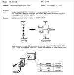
2/ Measure the voltage across that diode as the preset is varied. You should get at least 2.4 volts: 0 volts. I checked the diode with the diode setting on my multimeter and it reads OL in both directions (I removed one lead from the circuit). the last time when I measured it in the course of these works, it did ok. but it might have get hit afterwards. I had even soldered 4 diodes in series in order to simulate the 4x diode drop. I could put this in and measure then. I wait for your go on that.
SONY has a service amendment as to how to substitute that diode. I had already searched it, asking myself if it was the culprit. see attachment.
ongoing thanks...
Eschenborn
1/ Measure the DC voltage at the junction of the 0.22 ohm resistors: 0,3mV
2/ Measure the voltage across that diode as the preset is varied. You should get at least 2.4 volts: 0 volts. I checked the diode with the diode setting on my multimeter and it reads OL in both directions (I removed one lead from the circuit). the last time when I measured it in the course of these works, it did ok. but it might have get hit afterwards. I had even soldered 4 diodes in series in order to simulate the 4x diode drop. I could put this in and measure then. I wait for your go on that.
SONY has a service amendment as to how to substitute that diode. I had already searched it, asking myself if it was the culprit. see attachment.
ongoing thanks...
Eschenborn
Attachments
Last edited:
I would definitely replace the bias diodes with the transistor arrangement anyway. A BD139 should work well in place of the 2SD1585. You can make R2 adjustable to precisely control the bias
The low DC voltage is perfect... too perfect even 🙂 but lets run with that... and forget the bias problem for the moment because that will not stop the amp working.
Having zero volts across the diode does still point to a problem with the amp, however with the relay not operating and given the low offset it appears we might have more than one issue.
So lets change tack and quickly look at why the relay is not operating, because with zero volts DC at the 0.22 ohm junction (check this for both channels) that should allow the relay should operate correctly.
At this stage it doesn't matter if the amplifier itself is faulty or not. If you have no DC offset the relay should click over. Lets see if anything obvious is wrong here.
1/ Before going any further put the preset back to minimum resistance.
2/ Re-check that the offset really is zero for both channels.
The relay is powered (unusually) between ground and the negative rail.
3/ Locate R421 and make sure that the resistor is OK and that you have the negative 44 volts present on both sides of the resistor.
C407 (and C406) are mission critical parts and would be typical of parts that are highly stressed and that can and do fail. These form a voltage doubler arrangement and provide a high voltage DC bias supply for the relay driver.
The two driver transistors Q405 and Q406 are biased on via this supply and base bias resistor R416. These transistors turn on and connect the relay across the negative rail to power it (via the 680 ohm limiter R409).
4/ Measure the voltage on Q405 and 406 collectors. If the relay is powered this shpuld be at the negative rail (-44v). Worth checking... we never as we assume anything without confirming 🙂
So you should see zero volts there if the relay is not operating. Lets make sure.
5/ A quick check of the relay itself can be done by just shorting the collector and emitter of Q406. The relay should close instantly.
Lets see where that gets us.
We have two choices from here... we can continue to troubleshoot the relay section or we can simply over ride the relay and come back to that later and continue troubleshooting the amp if needed.
Here come my results. By the way, Mooly, your guidance truly helps me. Perfect step-by-step procedure for me which even makes me understand how the circuit functions. I am really grateful for that.
I'd leave that decision to you. Maybe check Q405 and Q406 out of circuit?
THANKS
Eschenborn
-> done1/ Before going any further put the preset back to minimum resistance.
offset is 0,015 mV on the right (bad) channel, -0,03mV on the good (left) channel2/ Re-check that the offset really is zero for both channels.
-> R421 looks good, -42,5V present on both sidesThe relay is powered (unusually) between ground and the negative rail.
3/ Locate R421 and make sure that the resistor is OK and that you have the negative 44 volts present on both sides of the resistor.
-> I changed C406 as it showed some heat traces, but presumably was still good (need to recap anyway). don't have the right value to replace C407 at hand right now, so left that in place, looks good. all the caps in this amp small of leaking electrolyte btw, never had that so strongly in any amp.C407 (and C406) are mission critical parts and would be typical of parts that are highly stressed and that can and do fail. These form a voltage doubler arrangement and provide a high voltage DC bias supply for the relay driver.
-> 0 volts on the collectors of Q405 and Q4064/ Measure the voltage on Q405 and 406 collectors. If the relay is powered this shpuld be at the negative rail (-44v). Worth checking... we never as we assume anything without confirming 🙂
-> closes instantly. nice sound to hear the relay close actuallySo you should see zero volts there if the relay is not operating. Lets make sure.
5/ A quick check of the relay itself can be done by just shorting the collector and emitter of Q406. The relay should close instantly.
We have two choices from here... we can continue to troubleshoot the relay section or we can simply over ride the relay and come back to that later and continue troubleshooting the amp if needed.
I'd leave that decision to you. Maybe check Q405 and Q406 out of circuit?
THANKS
Eschenborn
Last edited:
OK 🙂 lets stick with the relay for now and lets see if measurements get us anywhere rather than random pulling and checking of parts.
C407 despite its tiny value is actually a small reservoir cap for the high voltage bias supply for the relay driver. It's small so that the circuit can drop the relay out the moment the AC power is turned off.
It actually leads a hard life because the ripple component is large in relation to the cap value and caps used for this kind of thing suffer badly. That is most likely why a high voltage part was chosen, it would have a higher ripple rating than a 63v cap.
So...
Lets split the circuit in half and see whether the problem is in the protection and DC offset detector or whether it is a relay drive issue.
There are a couple of things we can do.
1/ Lift one end of R412. With that out of circuit the relay should operate. R412 is the only mechanism that can turn off the relay driver transistors, achieved by pulling C405 down to the negative rail.
If the relay operates then that section is basically OK.
---------------------------
If the rely doesn't operate we have a problem with the relay driver stage and those caps would be suspect. Leave the 6k8 isolated for now.
2/ R416 (150k) is also a possible suspect. Again its just a case that parts like this, a high value resistor on a high voltage supply, can and do fail.
We can measure the voltage on the base of Q406 and Q405 using the emitter of Q406 as the reference point.
You should see around +0.6v on Q406 base and 1.2v on Q405 base.
If they are low then check the resistor R416 first.
The transistors would be the last suspects.
I got it confused... will measure now correctly
...
or rather I confused the write up and measured correctly.
so:
Q406 Emitter --> Q405 Base: -2,2 V
Q406 Emitter --> Q406 Base: 0,01 V
...
or rather I confused the write up and measured correctly.
so:
Q406 Emitter --> Q405 Base: -2,2 V
Q406 Emitter --> Q406 Base: 0,01 V
Negative 2.2 looks a bit odd... and I'm going to revise my description of how it operates because I've spotted a couple of things... although it doesn't change the fault-finding approach.
So continuing there is actually another forward bias path I missed so lets just try and do this in a couple of easy moves.
Measure the Base/Emitter voltage of both Q403 and Q404. Note that Q404 isn't returned to the negative rail so you will have to measure directly across the transistor pins.
Both readings should be way below 0.6volts showing both are OFF
The other bias path was via R415/D407 and R415. So R415 also becomes a suspect.
A quick and dirty test you could do if its easy is to link out C403 and C404. The relay should operate. That test would apply if you did measure 0.6 volts on those two transistors.
R416 looks good, in circuit it measures 23,2 KOhm
You would have to measure these out of circuit. R416 should be 150k.
- Home
- Amplifiers
- Solid State
- Sony TA-3650 power rail resistors burn