That looks brilliant.
How should the trimpot be set then initially?
Well after some thinking... I'd set it so that the part of the swipe which is where the 1K resistor should be is set to max resistance, as you said, aka 5K.
If you test the set up on a battery (with series 1k) then it doesn't matter because you will see it swing through the whole range as you test it.
Once we know it works you can then set it for minimum voltage across the transistor... well at least to a voltage lower than would set the output stage in conduction. Lets say 1 volt.
Once we know it works you can then set it for minimum voltage across the transistor... well at least to a voltage lower than would set the output stage in conduction. Lets say 1 volt.
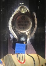
ok! I even found a longer screw with the right diameter to fix the "contraption" to the output device. today I should call it a day!
so I don't connect it yet to the PCB and test it with a 9v source and 1K series resistance instead. and will then report.
so I don't connect it yet to the PCB and test it with a 9v source and 1K series resistance instead. and will then report.
Don't rush it and definitely test it first. You need to be able to achieve at least 3 to 3.5 volts across the transistor (that would give lots of bias current) and also to be able to go as low as around 1 volt to give no bias at all.
With 3 volts across the transistor and 6 volts across the series 1k we have 6 milliamps flowing which matches the operating conditions in the amp.
With 3 volts across the transistor and 6 volts across the series 1k we have 6 milliamps flowing which matches the operating conditions in the amp.
Don't rush it and definitely test it first. You need to be able to achieve at least 3 to 3.5 volts across the transistor (that would give lots of bias current) and also to be able to go as low as around 1 volt to give no bias at all.
With 3 volts across the transistor and 6 volts across the series 1k we have 6 milliamps flowing which matches the operating conditions in the amp.
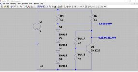
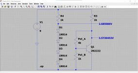
Yes, no worries. I'll test it now. The implementation looks like this at the moment (see pic).
Attachments
This is how the simulation shows it but remember it is transistor dependent. The pot is set to 4K/1k and then 1k/4K
I love this. Pretty enlightening. Thanks!
So next I'll report back from the 9V test.

Ok, here the results.
With the swiper on 5K, I get 0.6V across the transistor. By turning up the preset, I can go up to 4V, and beyond (didn't try in order to treat the transistor nicely).
What do you think? This seems in the ballpark you predicted.
With the swiper on 5K, I get 0.6V across the transistor. By turning up the preset, I can go up to 4V, and beyond (didn't try in order to treat the transistor nicely).
What do you think? This seems in the ballpark you predicted.
That all sounds good and you will not harm the transistor at all with the 1k resistor in series.
So you need it set to the low voltage (your 0.6V) for initially fitting to the amp.
So you need it set to the low voltage (your 0.6V) for initially fitting to the amp.
ok yes. very well!
so I'll wire the rubber diodes (the other one tested good as well) in, set them to max R (giving 0.6V across the transistor), leave the original presets bridged, and power the amp on on the DBT.
Then I'll set to factory bias using the new presets on the rubber diodes. did I get it right?
I'll probably come to this only tomorrow or Tuesday as I need to prepare stuff for the week (heavy workload), but it will be done soon. I feel close to the goal. at least I can see light at the end of the tunnel.
I think what I would do is this:
1/ Make sure you have the bulb tester fitted.
We have to decide now whether to use the original 2k2 preset to set the bias or whether to use our new preset on the transistor... I think I would do the following.
2/ Fit the new 'contraption'.
3/ Remove the link across the 2k2 preset and set it to the midway position.
4/ Switch the amp on and turn the new contraption preset to give the correct bias current as per the manual.
Does that make sense 🙂
5/ If it all seems OK then turn the bias down using the original preset.
6/ Go to full mains (no bulb) and reset the bias correctly using the original preset.
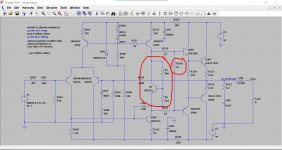
So it will look like this, the original preset at around 1.1k (I put 1k on the sim) and the new preset set to whatever gives the correct bias. From that point tweak the setting using the original control.
1/ Make sure you have the bulb tester fitted.
We have to decide now whether to use the original 2k2 preset to set the bias or whether to use our new preset on the transistor... I think I would do the following.
2/ Fit the new 'contraption'.
3/ Remove the link across the 2k2 preset and set it to the midway position.
4/ Switch the amp on and turn the new contraption preset to give the correct bias current as per the manual.
Does that make sense 🙂
5/ If it all seems OK then turn the bias down using the original preset.
6/ Go to full mains (no bulb) and reset the bias correctly using the original preset.
So it will look like this, the original preset at around 1.1k (I put 1k on the sim) and the new preset set to whatever gives the correct bias. From that point tweak the setting using the original control.
Attachments
I think what I would do is this:
1/ Make sure you have the bulb tester fitted.
We have to decide now whether to use the original 2k2 preset to set the bias or whether to use our new preset on the transistor... I think I would do the following.
2/ Fit the new 'contraption'.
3/ Remove the link across the 2k2 preset and set it to the midway position.
4/ Switch the amp on and turn the new contraption preset to give the correct bias current as per the manual.
Does that make sense 🙂
5/ If it all seems OK then turn the bias down using the original preset.
6/ Go to full mains (no bulb) and reset the bias correctly using the original preset.
So it will look like this, the original preset at around 1.1k (I put 1k on the sim) and the new preset set to whatever gives the correct bias. From that point tweak the setting using the original control.
Sounds good. I get it. It will take some days as I won't get at it tonight, and tomorrow is a new work week. I'll report back asap. The amp sits on my desk and calls for being finished.
Big thanks again!
no bias voltage :-(
good morning!
I was curious and started working on the amp before everything else this morning. Followed your procedure.
I discovered that he original presets (RT 351, RT 301) only have a range between 0 and 1,5k (because they are wired only with 2 pins?) I set them to 1k as per your simulation.
Amp plugged into DBT. Switched on. Amp opens relay.
I measured 0 volts bias at the measuring point (across the emitter resistor). This did not change at all by turning the preset on the new rubber diode up or down.
The zero bias voltage also did not change by turning the original preset up or down (I only tried a narrow range on that).
I checked for continuity of the connection between rubber diode and PCB. I also rechecked if I connected the right transistor pins. seems ok.
Both channels behave the same.
hm. (need to go back to "real" work now).
The original presets will be wired using the middle lead and one end lead. They should adjust from zero ohms up to the marked value of the preset.
It is remotely possible the value used in production was changed and that a 1k5 is fitted.
Also you can not measure the preset resistance in circuit because of other interactions.
Your new transistors collector (middle lead) should go to Q303 and the emitter to Q304.
So things to check... and lets be sure what we are measuring first. The bias current is the current flowing in the 0.22 ohm resistors connected to the output transistors.
The voltage you will see across these resistors is very small, only a few millivolts. 100 milliamps current would show as just 22 milivolts across either of those resistors. Be very careful not to short anything when measuring.
1/ First you can try just turning the original preset to its maximum resistance (which should be 2k2) and then see if your new bias control works.
We know the new transistor works OK because we tested it with the battery.
2/ If you still can not get any bias current to flow then we need to get an idea of how far off we are in terms of range of the new control.
We do that by measuring the voltage across the collector and emitter, just as we did with the battery test. You need to see approximately 2.5 volts before the stage will draw current.
This is the combined voltage needed to overcome the four base/emitter junctions of the driver and output transistors which will be around 600 to 700 millivolts for each one.
Thanks. That sounds systematic. I am confident!
I am going to do as you say asap (I am eager to get it going), and need to get some work done first.
Thanks again!
I am going to do as you say asap (I am eager to get it going), and need to get some work done first.
Thanks again!
- Home
- Amplifiers
- Solid State
- Sony TA-3650 power rail resistors burn