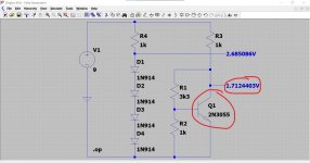
AWESOME.
you just simulated the amp!
Is the remaining crossover distortion something you'd find in any amp alike? or is it a weakness of that SONY?
and is the peak at the top end (very top of the top end) nasty? in danger of causing instability?
I replace the 2SC458 in a Kenwood KA-4000 with BC546's. I can't believe today that I did not make a single mistake in pin dyslexia. So it was a worthwhile choice electrically. I'd really prefer something with the same pin orientation, though, after the fresh mess I made with the SONY.
tonight's video night with my wife, so more tomorrow. I love LTspice!
Did you know that you can even play .wav files into a Spice simulation (the files are gone now) and record the result:
Welcome to the (virtual) listening room.
All Class AB amps have noticeable crossover distortion to some degree with no bias. Give it some bias and the crossover kink disappears.
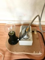
Stability can be a very real issue and so I'd recommend any major swaps of semiconductors to always use the bulb tester and also to follow up with a scope check of the output to make sure there is no oscillation present.
If you ever want to install LTspice for a play then I can make the simulation file 'click and run' so that you can probe around it and try changing things 🙂
Welcome to the (virtual) listening room.
All Class AB amps have noticeable crossover distortion to some degree with no bias. Give it some bias and the crossover kink disappears.
Stability can be a very real issue and so I'd recommend any major swaps of semiconductors to always use the bulb tester and also to follow up with a scope check of the output to make sure there is no oscillation present.
If you ever want to install LTspice for a play then I can make the simulation file 'click and run' so that you can probe around it and try changing things 🙂
Did you know that you can even play .wav files into a Spice simulation (the files are gone now) and record the result:
Welcome to the (virtual) listening room.
All Class AB amps have noticeable crossover distortion to some degree with no bias. Give it some bias and the crossover kink disappears.
Stability can be a very real issue and so I'd recommend any major swaps of semiconductors to always use the bulb tester and also to follow up with a scope check of the output to make sure there is no oscillation present.
If you ever want to install LTspice for a play then I can make the simulation file 'click and run' so that you can probe around it and try changing things 🙂
I'd love to. I'll be a very bloody beginner. I probably have also limited time in the next weeks to get deeper into this as the next major writing venture looms. I'll also ask my son, as he is doing a degree in this (informatics & engineering), so he'll probably enjoy if I had some practice. thanks again!
I'm on a mac, though. That might pose a major obstacle?
I'll assemble a proper DBT. Totally convinced 🙂 And finally my "new" scope proved its right to exist!
Did you know that you can even play .wav files into a Spice simulation (the files are gone now) and record the result:
Welcome to the (virtual) listening room.
so that's pretty crazy. I can "make" changes on my amp's layout (e.g. increase size of coupling caps), and I will be able to hear it???
I've never ever used a Mac but I do see an official version on the LT site. Scroll down.
LTspice | Design Center | Analog Devices
If you click my signature line... you've probably seen it anyway... then it tells you how to install and use LT.
LTspice | Design Center | Analog Devices
If you click my signature line... you've probably seen it anyway... then it tells you how to install and use LT.
so that's pretty crazy. I can "make" changes on my amp's layout (e.g. increase size of coupling caps), and I will be able to hear it???
If its something that would give an audible change then yes.
Taking up the Restoration Work
After two months of a lengthy break (and two long work assignments later) I am trying to finish my restoration work on the Sony TA-3650 amp.
And thanks again, Mooly, for guiding me to the rescue in the first phase. I hope everyone is fine and safe.
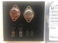
I hope I'll steer clear of major glitches now. I already replaced the wrong transistor type I had put on position Q351 (as I had no PNP types at hand then). I have now put in a pair of 2N5401 (needed to bend the legs as they are of a different pinout as the original double package 2SA884.
I'll also replace the output devices of the repaired channel with MJ21194 and MJ21193 respectively.
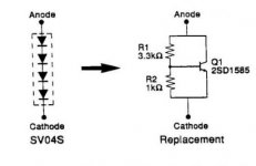
But first I'll construct the "rubber diodes" according to the SONY service bulletin (it is in this thread: Was kann ich verwenden, um eine SV-04F-Vorspannungsdiode zu ersetzen? - Antworten Hier).
The SONY bulletin gives 2SD1585 as the transistor I should use (plastic casing). I could only find a BUT56AF, but assume the specs will be fine. I'll construct a tiny PCB as per the service bulletin.
Can I test my contraption (the "rubber diode") once it is finished with the diode test function of my DMM as if it were a true diode?
Thanks!

After two months of a lengthy break (and two long work assignments later) I am trying to finish my restoration work on the Sony TA-3650 amp.
And thanks again, Mooly, for guiding me to the rescue in the first phase. I hope everyone is fine and safe.
I hope I'll steer clear of major glitches now. I already replaced the wrong transistor type I had put on position Q351 (as I had no PNP types at hand then). I have now put in a pair of 2N5401 (needed to bend the legs as they are of a different pinout as the original double package 2SA884.
I'll also replace the output devices of the repaired channel with MJ21194 and MJ21193 respectively.
But first I'll construct the "rubber diodes" according to the SONY service bulletin (it is in this thread: Was kann ich verwenden, um eine SV-04F-Vorspannungsdiode zu ersetzen? - Antworten Hier).
The SONY bulletin gives 2SD1585 as the transistor I should use (plastic casing). I could only find a BUT56AF, but assume the specs will be fine. I'll construct a tiny PCB as per the service bulletin.
Can I test my contraption (the "rubber diode") once it is finished with the diode test function of my DMM as if it were a true diode?
Thanks!

Attachments
Just trying to pick up on where the thread was at 🙂
The transistor mod (rubber diode) can not be tested on a meter. You have to be 100% certain you build it correctly and that you set the preset in the position to give minimum bias before you power up.
The BUT device is primarily a switching transistor for SMPS and I have doubts over its suitability tbh because I think it will have very low gain at low currents. Try it though but use the bulb tester for safety.
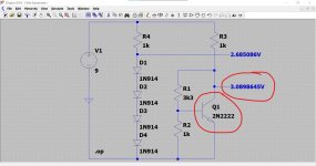
You could test the 'contraption' with a 9 volt battery and series resistor to limit current. You would measure the voltage across the transistor as you vary the preset. It should go from close to zero to at least 3 volts. You would need something like a 1k series resistor.
The transistor mod (rubber diode) can not be tested on a meter. You have to be 100% certain you build it correctly and that you set the preset in the position to give minimum bias before you power up.
The BUT device is primarily a switching transistor for SMPS and I have doubts over its suitability tbh because I think it will have very low gain at low currents. Try it though but use the bulb tester for safety.
You could test the 'contraption' with a 9 volt battery and series resistor to limit current. You would measure the voltage across the transistor as you vary the preset. It should go from close to zero to at least 3 volts. You would need something like a 1k series resistor.
Hi Mooly, good to have you around again! And thanks for replying with lightning speed.
I was happy as I had found a plastic case substitute... too bad then. I'll test.
I have also built a DBT in the meantime (did I already proudly present it?) so everything will be a bit safer.
thanks!
I'll go on constructing.
I was happy as I had found a plastic case substitute... too bad then. I'll test.
I have also built a DBT in the meantime (did I already proudly present it?) so everything will be a bit safer.
thanks!
I'll go on constructing.
It may well be OK, you'll just have to try it for real and see 🙂
You might have mentioned the DBT but its a zillion posts back in time for me 😉
You might have mentioned the DBT but its a zillion posts back in time for me 😉
Before you make a board just tag the preset onto the transistor and test it with the series resistor. It only takes two minutes.
Before you make a board just tag the preset onto the transistor and test it with the series resistor. It only takes two minutes.
I've just found the link you posted... no preset. Try it and see what voltage you get across the transistor (with a 1k series resistor and 9 volts).
Attachments
Neat job 🙂
So... I think this transistor mod will be device critical if you use fixed resistors. Much better if you make the lower resistor a preset and then the bias can be set precisely. Something like a 2k2 preset.
I'll look in later.
So... I think this transistor mod will be device critical if you use fixed resistors. Much better if you make the lower resistor a preset and then the bias can be set precisely. Something like a 2k2 preset.
I'll look in later.
Attachments
Thanks.
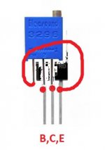
I have only 5K presets at the moment. Will they suffice (be sensitive enough)? They are those blue multi turn ones.
And how do I connect them? They have three pins. The existing bias pots in the amp are only connected with two pins to the circuit; normally all three are used. Bad source of errors for someone like me.
Thanks.
I have only 5K presets at the moment. Will they suffice (be sensitive enough)? They are those blue multi turn ones.
And how do I connect them? They have three pins. The existing bias pots in the amp are only connected with two pins to the circuit; normally all three are used. Bad source of errors for someone like me.
Or could I just tag the transistor to the three pins of the preset? Then 5K would seem to be just right.
Well you have two choices, and yes 5k should be workable.
Choice 1 is just to replace the lower 1k with the preset. You use the middle lead (wiper) and either of the other end leads. Leave the other lead free.
Which end lead you use determines which way the control operates and it really doesn't matter as long as you know which way it operates and set the preset correctly initially.
You need it set to give 5k resistance as that will give minimum bias.
------------------------
Choice 2 is the economy version and is often used. You wire the middle lead (wiper) to the base and the other leads go to collector and emitter.
Disadvantage of choice 2 is that if the wiper of the preset were to go open circuit then the bias would shoot to maximum and probably destroy the output stage. Is that likely... not really with a new multiturn pot.
Choice 2 lends itself to constructing without a PCB.
Or could I just tag the transistor to the three pins of the preset? Then 5K would seem to be just right.
Something like that 🙂 Yes 😀
- Home
- Amplifiers
- Solid State
- Sony TA-3650 power rail resistors burn