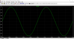
This is what no bias looks like at the output of a typical amp. Look at the zero crossing point.
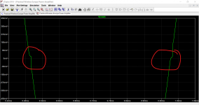
And zoomed in.
That level of distortion would be very very audible on a sine wave and give what should be a pure tone a harsh character.
And zoomed in.
That level of distortion would be very very audible on a sine wave and give what should be a pure tone a harsh character.
Attachments
No bias will cause possibly faintly audible distortion at low levels. A pure (it must be pure to tell) sine wave of 1khz or higher is good test.
Many years ago... how old is this amp 😀 we used to say that -/+100mv or lower was acceptable as an offset.
If you think about it, 100mv across 8 ohms is only 12.5 milliamps and the power dissipated in 8 ohms is just 1.25 milliwatts
TRUE audiophiles would cringe now I assume.
I'd be good with 100mV.
It's a gift to a non-audiophile, and needs to be reliable before all.
The amp is from the mid seventies I think.
I could put in a couple of those 2SB649A in place of the dual differential package, though 🙂 like I did in the other channel, tied together. just two know what that will give. Now that I have the living room table dim bulb lamp tester...
but frist try with direct mains.
I did not hear distortion, but I might be too deaf. The slight non-refinement in sound probably is due to the still original main PS cap (double can). I'd love to not do the work of fitting two single caps in there, drilling holes, building an adaptor PCB... but for durability's sake I should change ALL electrolytics.
Interesting choice... 2SB649's for a differential input stage. Perhaps like the curates egg, good in parts 🙂
Normally high gain devices with low inter junction capacitance are preferred for input stages but as always it is often a case of what you have or what you can get.
The dual transistor package has two devices of near identical performance, in other words they are well matched, much closer matched than just hoping two devices of the same number match... however... depending on the circuit the unmatched parts might actually help reduce an offset. If that makes sense.
When using separate transistors you might find the offset much better with the devices swapped around. For example an offset of +0.3 volts might change to -0.1 volts if you swap them around.
If you have a test CD or MP3 file of 1kHz then you might hear the distortion.
I'll have to leave it for tonight but if needed we can look at ways of tweaking the offset right down (maybe 😉)
Interesting choice... 2SB649's for a differential input stage. Perhaps like the curates egg, good in parts 🙂
Normally high gain devices with low inter junction capacitance are preferred for input stages but as always it is often a case of what you have or what you can get.
The dual transistor package has two devices of near identical performance, in other words they are well matched, much closer matched than just hoping two devices of the same number match... however... depending on the circuit the unmatched parts might actually help reduce an offset. If that makes sense.
When using separate transistors you might find the offset much better with the devices swapped around. For example an offset of +0.3 volts might change to -0.1 volts if you swap them around.
If you have a test CD or MP3 file of 1kHz then you might hear the distortion.
Or I could see it on the scope 🙂
It's true that I threw in the 2SB649s because I had nothing else here. So maybe I should order some high gain devices with low inter junction capacitance and then try to find the best match – for both channels.
Interesting choice... 2SB649's for a differential input stage. Perhaps like the curates egg, good in parts 🙂
Haha... I am obviously also learning in the language domain in this process. So the 2SB649s are hopeful monsters, then 🙂
I'll dig into alternatives.
I'll have to leave it for tonight but if needed we can look at ways of tweaking the offset right down (maybe 😉)
That makes me curious 🙂
And probably I should ask you what devices you'd suggest to look for to replace the the dual pair at Q302 and the curate's substitutes.
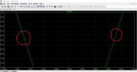
This is what no bias looks like at the output of a typical amp. Look at the zero crossing point.
And zoomed in.
That level of distortion would be very very audible on a sine wave and give what should be a pure tone a harsh character.
ah! saw this only now. I'll test. I could use the scope again I assume 🙂
I measured offset again with the amp fully on the mains. It's now much better, 5mV for the good, -8mV for the repaired channel. still going up and down a bit, but in the 1-digit-range.
Was that the effect of the DBT? Or is my DMM a bit tricky at those low voltages? It's no Fluke, alas. But now the values seem quite settled.
Good night!
The crossover distortion would probably only be visible on the scope if you had a load attached. The really high gain of the amp (overall open loop gain) tends to mask it.
It occurs because of the 'dead band' of non biased output pairs, they don't conduct until there is that magic 0.6v across the B-E junction to turn them on. So tiny signals (around the zero of crossover point) are effectively not seen.
So it looks like we haven't a problem with offset and that the reason for seeing it was the DBT, probably because the rails were a little lower than normal and that the regulation of rails is poor with a bulb in circuit. That said, much is down to the design and modern set ups would hold a good DC offset over a massive change in supply voltage rather than an amp being designed for low offset on a given supply.
Its a non issue, the goal posts moved over the years.
Had the offset been permanently a bit high then we could have looked at tweaking the current source feeding the diff pair and/or R304
The 2N5401 is a good generic small signal device although there are other better still but its a case of what you can get and get without them being fakes.
MPSA56 is another popular one for PNP's.
Good morning, and thanks!
I am happy that we seem to be good on the offset. And I am going to order some of those small signal devices. Thanks for the suggestions. I know, it's crazy how easy one is sold fakes. Maybe less risk with the most generic ones.
I don't even know for 100% sure if the new output transistors are true or fakes. They look good, but I bought them at ebay (Mouser charges a high shipment fee if I don't order for more than 50 euros).
I don't hope my in-law will turn up the amp and then they'll die on him.
Hmm... we tend to steer clear of ebay tbh. That's not to say everything is fake, but so much is. We always advise to buy from recognised distributers unless you can be 100% sure of the quality.
Have you seen this. It is old but continually posted to :
My Transistors, original or copy?
The 2N5401's are 150v rated, the MPSA's only 80 I think but that should not be an issue as they only see around 45volts in your amp.
There are plenty of others although the numbers escape me without looking them all up.
Hmm... we tend to steer clear of ebay tbh. That's not to say everything is fake, but so much is. We always advise to buy from recognised distributers unless you can be 100% sure of the quality.
Have you seen this. It is old but continually posted to :
My Transistors, original or copy?
Oh dear. I looked at that last page of the thread. It means that I actually need to replace the "new" outputs of that repaired channel before serious operation as they are of doubtful origin... and show these blue glass sealings on the bottom.
Oh heck 🙁
I'm no expert on identifying fake parts visually although sometimes fakes can look obviously suspect.
Do a bit of research on what you actually got and lets see if they may or may not be fake.
I'm no expert on identifying fake parts visually although sometimes fakes can look obviously suspect.
Do a bit of research on what you actually got and lets see if they may or may not be fake.
Actually one possible way might be to look at the forward B-E voltage (when they are biased correctly) because modern parts tend to use slightly different doping techniques and so that means the B-E forward voltage might (only might) give a clue.
If yours are genuine then they should be similar to the good channel. If you see big differences (like 0.48v vs 0.6v) then that might be a clue.
If yours are genuine then they should be similar to the good channel. If you see big differences (like 0.48v vs 0.6v) then that might be a clue.
Actually one possible way might be to look at the forward B-E voltage (when they are biased correctly) because modern parts tend to use slightly different doping techniques and so that means the B-E forward voltage might (only might) give a clue.
If yours are genuine then they should be similar to the good channel. If you see big differences (like 0.48v vs 0.6v) then that might be a clue.
Thanks! I am going to do that. Pretty interesting. I have some vintage devices coming in (but even there...) so possibly could swap. What I have is:
R-CH (repaired)
2N3055
MJ5955 (both ST Electronics)
L-CH
2SD551 (Sanken)
2SB681 (Toshiba)
Those both look original... or at least in there for a long time. I did not keep the other pair, and unfortunately forgot to check if they were the same (some months ago).
I have RCA 2SD3055 NOS (hopefully) and BDX18 coming in.
Here is an interesting site on the anatomy of SN3055 originals and fakes (ahem). In german though.
Now need to finish that text.
The 2N3055. The indestructible transistor as a college lecturer once described it... if only Lol.
The 2N3055/2955 are 60 volt rated. Now that might seem enough given that you have -/+45v rails... but is it?
As the output swings toward the positive rail putting voltage across the load, the upper transistor sees less voltage across it (but more current) while the lower one see no current at all but an ever rising voltage. The collector is at the negative rail, so -45v and the emitter is being pulled higher to toward the positive rail by the upper conducting NPN device.
And vice versa for negative signals.
So each output transistor and each driver can see under worst case conditions the full total supply of 90 volts. Ooops 😀
There is also something called 'Secondary Breakdown' that affects transistors used near to their maximum voltage rating while conducting large currents and that caues the transistor to fail unexpectedly even though no overall parameter has been exceeded.
So ideally you want 100+ volt devices here.
The MJ21194 and 21193 are well liked modern parts.
Attachments
Also... the 2N3055/2955 are some of the most likely devices to be used for marking to something else, not the other way around.
Also... the 2N3055/2955 are some of the most likely devices to be used for marking to something else, not the other way around.
So mine might not be counterfeits, but wrong nonetheless. Or both 🙂
Thanks for all the information. Good to know that. Interesting stuff. I only looked at the wattage while choosing the devices. So it seems reasonable to do one big purchase at Mouser for all the silicon.
I wonder what you would recommend in order to replace 2SC2458. Some suggest 2SC2240, others 2SC945. 2SC2458 is ubiquitous in the old Kenwoods I have.
Counterfeit we don't know for sure, but at 60 volt they are underrated which is enough reason in itself.
The BC546 (different pin outs) could be a good fit for the 2SC2458... there are just so many though. Its maximun current rating is a bit lower but usually small signal parts like these aren't run anywhere their Ic rating. It really depends on the application.
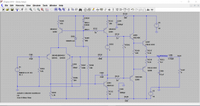
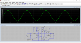
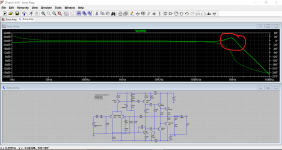
I've just put your Sony into a simulation which is quite interesting to see how it behaves.. The response is a bit peaky at the top end (way way above audio range) and that could be down to modern transistor characteristics. The original output devices were probably quite slow.
It's interesting though.
You can see the low level crossover distortion at no bias. Its small as mentioned earlier because the open loop gain of the amp is so high that there is lots of active 'correction ability' available.
The BC546 (different pin outs) could be a good fit for the 2SC2458... there are just so many though. Its maximun current rating is a bit lower but usually small signal parts like these aren't run anywhere their Ic rating. It really depends on the application.
I've just put your Sony into a simulation which is quite interesting to see how it behaves.. The response is a bit peaky at the top end (way way above audio range) and that could be down to modern transistor characteristics. The original output devices were probably quite slow.
It's interesting though.
You can see the low level crossover distortion at no bias. Its small as mentioned earlier because the open loop gain of the amp is so high that there is lots of active 'correction ability' available.
Attachments
- Home
- Amplifiers
- Solid State
- Sony TA-3650 power rail resistors burn