I guess it would be interesting to do an A/B comparison of the two different versions of this player. The version this thread is based on is perfectly decent in itself, but is outclassed when directly compared to more 'audiophile' oriented players.
Interesting, thanks 🙂
Interesting, thanks 🙂
I completely agree with that - although as players go, it was quite decent in it's day (and probably still quite good when compared against similar 'budget' players of today).
I've had a 227ESD for a few years now, and that is undoubtedly better.
I've had a 227ESD for a few years now, and that is undoubtedly better.
Hello,
I'm new to all of this, but I've run into an issue with my CDP 790.
I get the 'no disc' message when I load in a disc.
The disc/motor does not spin at all.
The last thing to happen before the fault was that track playing skipped.
Any help troubleshooting this would be much appreciated.
I'm new to all of this, but I've run into an issue with my CDP 790.
I get the 'no disc' message when I load in a disc.
The disc/motor does not spin at all.
The last thing to happen before the fault was that track playing skipped.
Any help troubleshooting this would be much appreciated.
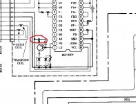
The first check is a quick visual one to determine if the lens performs a focus search operation when the tray closes. Closing the tray (no disc in) should see the lens move up and down 3 times. The laser should also be lit during this brief period.
The laser would only be lit during this brief period and may not be easy to spot. The fact it bobs twice suggests the focus search routine is OK... three 'bobs' is common on many players but not all. We have to say that's normal at this stage.
You have to make a judgement call now, do you pursue in depth testing to try and prove the pickup is faulty, or do you simply replace it first and then take things from there.
You have to make a judgement call now, do you pursue in depth testing to try and prove the pickup is faulty, or do you simply replace it first and then take things from there.
You could monitor the laser diode current by measuring the voltage across its feed resistor located on the pickup but that is not easy and would require you to solder wires to get a safe connection. Genuine original Sony pickups used to have the current value incorporated into the pickup serial numbers last three digit. For ex 564412589 would be 58.9 milliamps. You would see that current during the focus search operation.
You could use a scope to check if the Fok line sensed anything as the lens attempts to focus on a disc.
If all the supplies are good and the pickup is in the right place (and moves back to the inner position if you manually move it outward along the sled when the tray is open and closed) then a faulty pickup is a fair guess at this point.
Attachments
Thanks! I don't have the proper equipment for those checks, so I'll probably just get another pickup.
I have restored two identical players, and ordered the KSS240 from Ebay. The first one worked OK, The second one not, so I ordered another but did not Return it since I have fiddled with the pots. The third one is working also Ok. Rule of dumb, get two.
Hi MAACO,
Never touch the controls on the heads. One is the laser power control and if you drive it too far high, it will suddenly stop working ... forever.
-Chris
Never touch the controls on the heads. One is the laser power control and if you drive it too far high, it will suddenly stop working ... forever.
-Chris
Replaced the KSS240, and it plays again, hurrah! The stop and pause buttons probably have some contact issues, but I don't use them all that much, so will leave them for now.
 good to hear its working.
 The buttons (tact switches) should be available generally plus, they were used extensively on VCR's and that kind of thing and so there should be millions around if you look.
Just picked up an old CDP-X111ES (CDP-791 in Europe) with the same CXD-2552 DAC and also thought that it sounded bright/thin. Mine had a TL082 and NE5532 in the output, both DIP. It also had 47μF electrolytic coupling capacitors at the output; thinking that they might have something to do with the apparent thinness, I replaced them with 1000μF Panasonic FRs, which are bypassed with 1μF polyester and 0.01μF polypropylene film caps.... Listening trials revealed what I would describe as a typically bright and somewhat "thin" sounding player. It was up against stiff competition though in the form of my old Micromega Stage 2 and the Stages' successor, a Marantz Pearl-Lite SA-CD. I suppose that outcome is absolutely to be expected although I shall look at future mods for the Sony. The analogue stages use SIL package NE5532's (why couldn't they use DIL) and incorporates both "hard" relay muting to ground and "soft" bjt muting. Something for future work maybe.
IMO, it sounds much better with the new capacitors. The bottom end is now very deep... well, as deep as the recording provides. Also replaced the op amps with ADA4627-1s and OPA211s. From what I gather, the major limiting factor with these players is the analog section. While making modifications, I tried out a variety of capacitor combinations, making several A/B comparisons with my modded TC Impact Twin (using TOS) and listening with a pair of K702s. With the changes noted above, the X111ES now sounds better to my ear.
The CD790 uses only -/+5v rails for the opamps and that is a major limitation because some opamps will not allow the full output to be developed without clipping.
Yours sounds a little different if there is a TL082 in there, perhaps it is being used as some kind of servo as that would be an ideal application for the TL082 opamp.
Yours sounds a little different if there is a TL082 in there, perhaps it is being used as some kind of servo as that would be an ideal application for the TL082 opamp.
If I recall correctly one can up the +/- 5V supplies in this one by using Schottky diodes and 6V regulators which makes quite some impact. One has to measure the current voltages first if there is enough headroom (again, if I am right). Also check if it is only the output stage that is fed by the regs. I have seen so many CD players that I lost count and details.
With modern LDO regs it should certainly work out but using low noise types is mandatory.
With modern LDO regs it should certainly work out but using low noise types is mandatory.
Last edited:
The CDP790 unfortunately uses the same rails to supply all the processors and servo chips unfortunately, however the headphone amp runs on -/+10 to 12 volts (depending which bit of the diagram you look at 😉) but this is unregulated.
So there is some wiggle room for anyone keen enough to experiment.
So there is some wiggle room for anyone keen enough to experiment.
Aha so this is one you can put a new +/- PSU board in fed by that unregulated voltage. +/- 6V is enough for the opamps but it would not hurt to make it +/- 7V. Still possible with standard regs. With ultra low noise LDO like LT3042 and LT3094 you can make it +/- 9V.
Shared rails for all the electronics like it is now will not give best performance.
Shared rails for all the electronics like it is now will not give best performance.
Last edited:
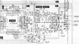
Below is a photo of the X111ES output section. It looks similar to the European CDP-790.The CD790 uses only -/+5v rails for the opamps and that is a major limitation because some opamps will not allow the full output to be developed without clipping.
Yours sounds a little different if there is a TL082 in there, perhaps it is being used as some kind of servo as that would be an ideal application for the TL082 opamp.
Perhaps you can tell me how the TL082 is used? I've got a pair of ADA4627-1s there at the moment. From the datasheet, it looks like the ADA4627-1 has a slightly lower output voltage limit than the TL082 and is operating at the bottom of it's voltage range. The OPA211 is rail-to-rail output, in place of the NE5532. Haven't heard any audible distortion. Do you think headroom is a serious issue here? Guess I could hook it up to a scope with a 0dB test signal and see.... worthwhile?
On the X111ES, the RC4556 headphone circuit is powered by +/-5V, regulated. Both analog and digital sections share the same supply. I've upped the 470μF caps on the analog rails to 1000μF Panasonic FR and the 470μF on the digital 5V rail to 3300μF Panasonic FM, with another 1000μF FR on the DAC's analog 5V rail. I also increased the 100μF caps in the headphone section to 1000μF FRs.
In this design, increasing the main rail voltage would also affect the digital section. Not sure if it would be a good idea to go over 5V there.
Overall, I'm wondering how much of a performance limitation the shared supply might be. Would it be measurable or audible if separate supplies were used or if the current supply voltage were increased? I can't say I noticed much or any difference after increasing the digital supply capacitance. However, I did notice a very audible improvement in sound after increasing the size of the output coupling capacitor and adding the film bypass caps; this, along with the high performance op amps, definitely made the most noticeable improvement in sound quality.
Attachments
- Home
- Source & Line
- Digital Source
- Sony CDP790 and KSS240 Restoration Project