Before attempting those two options there is something else you might want to try. Philips ran the CX7934 at 96Fs in at least one of their players. It might be worth trying.Many thanks for the clarification!
But mathematics are not my strength, how do I calculate the common frequency?
Yep, found it, in a CD303, but Philips schematics are PITA - did not yet find reliable data that 4.2336MHz feed pin 16 / A813.Before attempting those two options there is something else you might want to try. Phillips ran the CX7934 at 96Fs in at least one of their players. It might be worth trying.
The 4.2336MHz base frequency (lower left) gets heavily computed before being submitted to A813 (upper right):
And of course no signal charts ... So someone needs to measure, I have no CD-303.
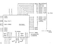
Sony CDP-101, same chipsets, I assume MSM2158 (Philips) MSM5128 (Sony) are just a typo:
Another finding: I did built a SPDIF-output for a Nakamichi player with the second generation CX23035 and DIT4192.
There were many cheaper players sold at that time with the CX23035 feeding the CDP-101's CX20017 DAC, like the Sony CDP-30.
Looking at the CX23035 datasheet, (serial) audio data output can be set between two's complement and offset binary.
It is set two's complement in the Nakamichi player and CDP-30. So I think data will be read by the DIT4192.
I did some further research, the CX7934 of the Philips CD-300 is also used in the identical Philips CD-200.Before attempting those two options there is something else you might want to try. Phillips ran the CX7934 at 96Fs in at least one of their players. It might be worth trying.
The service manual of the CD-200 has also measurement charts, the CX7934 runs on 8.64MHz, like in the Sony CDP-101
The circuit I posted does the conversion from 4.2366MHz to 8.64MHz.
Data about this can be found on page 86, test point 77:
https://elektrotanya.com/philips_cd200_sm.pdf/download.html#dl
So maybe this could be rebuild,
using a 11.2896MHz or 16.9344MHz clock as reference but I assume using a clock of those frequencies,
feeding the digital transmitter and being synced to the Sony's wordclock would be simpler, but have more jitter...?
Last edited:
Hi Salar,
You also started a thread on Diyaudio, As i wrote in my email ,
"
I had a look at some various usage of the CX7934 in Sony and Philips Players,
In the Sony, Serial Data is on pin 17 and bit clock on pin 32
The bit clock will be something like 88.2 kHz its 2 x 44.1
when i look a the Sophi usage in a philips player als 16 bit are parallel Da01 tot DA16 and the DA16 is inverted (binary offest ? )
There is used in a stopped clock configuatrion …
If you have a look at the the PCM53 PDF the is some explanation of the timing diagram witch the CX7934
We need a good datasheet off the CX7934 , i think the CX7934 can be set in different modus.."
I had a closer look , please check pin 37 PSSL ( PPSL ) is in the sony connected to ground , in the philips on the Sophie board its connected to +5 volt
I think the CX7934 on the Sophi board is in a different Mode
Thumbs up! The CX20017 accepts serial mode only, correct? Also, serial data is not different from later generations, so I assume only fs needs to be adressed.
So the goal will be to take a 16.9344Mhz master clock driving the DIT4192 transmitter
and to use this clock also for generating 8.6436MHz driving the CX7934.
A little bit conflicting:
In the CDP-101 service manual the frequency given is 8.6MHz,
but in the very identical CDP- 400 / 501 / 610 / 701 the number is 8.6436MHz.
The training document for Sony engineers says it is 8.64MHz for the CX7934.
Last edited:
Or the other way round: An 11.2896 or 16.9344MHz clock driving the transmitter
that is be synced either to the Sony's internal bitclock, (about2.16MHz) wordclock (88.2KHz) or L/R clock (44.1KHz).
that is be synced either to the Sony's internal bitclock, (about2.16MHz) wordclock (88.2KHz) or L/R clock (44.1KHz).
Scratch that, 96Fs will not work. Thought I saw it somewhere a long time ago but most likely mistaken. Can't see Philips using a PLL/VCO setup if the CX7934 would work directly with CLOX. Anyway that is a possible solution to bridging the clock domains. Philips get around the different clock domains by using a PLL/VCXO slaved to CLOX (96Fs) to generate the clock XTAL for the CX7934. Problem solved, just copy Philips.
Ok, many thanks.
But I my knowledge does not stretch that far to even copy.
So, looking at the Philips schematics from post #44:
I would like to use a 16.9344MHz clock to drive the digital transmitter.
This is exactly 4 times of the 4.2336MHz Philips used.
I do not know if the
IC 6660 - 74LS368AN HEX TRI-STATE INVERTING BUFFER
attached to the 4.2336MHz Xtal can compute faster frequencies than 5MHz,
but it is still being produced and availabe.
All other ICs in the Philips schematics from post #44 are also available:
IC 6661 - 74LS92N DECADE COUNTER; DIVIDE-BY-TWELVE COUNTER; 4-BIT BINARY COUNTER
IC 6662 - 74LS93N DECADE COUNTER; DIVIDE-BY-TWELVE COUNTER; 4-BIT BINARY COUNTER
IC 6663 - 74LS08N QUADRUPLE 2-INPUT POSITIVE-AND GATES
IC 6664 - HC4046AN PHASE LOCKED LOOP WITH VCO
IC 6665 - SN74LS624N VOLTAGE-CONTROLLED OSCILLATOR (can be found right in the schematics, the name/designation is out of view)
BC558 TRANSISTOR.
First question: Which of the ICs do I need?
To me it looks like IC6661 and 6662 are not needed as they provide clock signals
for the servos but not the CX7934.
Oh, by the way, I guess we agree that the fs is a no - brainer as it is defined by the bitclock. The higher, the more fs.
Last edited:
Usually Fs for PCM is the frame clock/word clock frequency (e.g. 44.1kHz). IOW, its how many samples per second. The bit clock is for the serial data, which carries the bit-depth value (amplitude) for each sample.
For DSD, Fs is the bit clock.
For DSD, Fs is the bit clock.
Real world measurement of the CDP-101 base frequency of 8.64(2)MHzA little bit conflicting:
In the CDP-101 service manual the frequency given is 8.6MHz,
but in the very identical CDP- 400 / 501 / 610 / 701 the number is 8.6436MHz.
The training document for Sony engineers says it is 8.64MHz for the CX7934.
the bitclock of 2.16(05)MHz
and Wordclock of 88.2 / 88.19 KHz:
Last edited:
For very different reasons.Oh, by the way, I guess we agree that the fs is a no - brainer as it is defined by the bitclock. The higher, the more fs.
We are nearly 40 years on from that schematic. We can do a little better these days.So, looking at the Philips schematics from post #44:
Many thanks in advance! I assume there are still many first generation players out there, so this mod
might interest others.
might interest others.
- Home
- Source & Line
- Digital Source
- Sony CDP-101 - adding S/PDIF-Output - looking for 4.2336 base frequency