here is my take on the subject.I see you post these graphs a lot. May I ask what you see in these and how they help you determine whether or not an amp is working well or not? What are you looking for when you look at them?
With thd numbers in the <0.01% range many argue you will never hear it so who cares.
with thd numbers <1% which btw was an originally definition of hi-fi, tubes and transformers era, the spectral harmonics are apparent.
It is known (tested by monkeys 🙂 that even order harmonics,2nd,4th .. are more acceptable or less annoying than odd order harmonics,3rd,6th ...
It comes down to a lot of personal preferences, opinions, on spectral content/distribution in the fft, quantity/type which are acceptable and which are not.
The goal is obviously to have none or minimal spectral hash, so you can say the amp only amplifies the input signal and nothing else.
Last edited:
the rest
Attachments


Last edited:
That is my problem. I don't know what the graphs indicate.
Terry, I will try to explain in a nut shell tomorrow.
different unfinished Board in Dip Trace
[special= ]%[/special]
Hi Valery,
I follow and view detailed work of Thimios and you on little things now.
Last days i was busy with DT and have a started little work to board like VLatFet in through hole.
Now it needs a mentor to advise something, but how i can send the dip file-
that point i difficult find solution to transform- what ever works....grrrrrr. 😕
The big Pattern areas and other refinement is to learn to came up to good pcb.
[special=
]%[/special]Hi Valery,
I follow and view detailed work of Thimios and you on little things now.
Last days i was busy with DT and have a started little work to board like VLatFet in through hole.
Now it needs a mentor to advise something, but how i can send the dip file-
that point i difficult find solution to transform- what ever works....grrrrrr. 😕
The big Pattern areas and other refinement is to learn to came up to good pcb.
[special=
Hi Valery,
I follow and view detailed work of Thimios and you on little things now.
Last days i was busy with DT and have a started little work to board like VLatFet in through hole.
Now it needs a mentor to advise something, but how i can send the dip file-
that point i difficult find solution to transform- what ever works....grrrrrr. 😕
The big Pattern areas and other refinement is to learn to came up to good pcb.
You can zip it and upload the file.
Okay Valery, I'll let you drive Terry's car, I promise to be a quiet back seat driver 🙂 while Valery squirrels up his nuts 🙂
Terry I want to hear Valery explain...He is clear and understandable.
I take the graphs thimios posts to show distortion. Often a graph showing the noise floor is shown. Then Showing the output when a sign wave of some frequency is injected into the amp. Any output graphed other then the inputted frequency is noise or distortion.
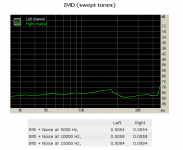
sometimes we see a graph that looks like a sweep showing the 2nd and 3rd distortion components of the thd compared to frequency. (see post 343)
Valery early in the development shows a graph of phase versus frequency I assume from the simulator. I believe that if the phase gets too far out in the frequency that the amp works in then the negative feedback gets messed up.
This is how I see it....I could be wrong on all counts...I often am...
I take the graphs thimios posts to show distortion. Often a graph showing the noise floor is shown. Then Showing the output when a sign wave of some frequency is injected into the amp. Any output graphed other then the inputted frequency is noise or distortion.
sometimes we see a graph that looks like a sweep showing the 2nd and 3rd distortion components of the thd compared to frequency. (see post 343)
Valery early in the development shows a graph of phase versus frequency I assume from the simulator. I believe that if the phase gets too far out in the frequency that the amp works in then the negative feedback gets messed up.
This is how I see it....I could be wrong on all counts...I often am...
evanc
I'm in Brooklyn, we should think about starting a northeast audio club if one hasn't already been established. I may not be Valery but I think I can explain the graphs so everyone can understand them.
vzaichenko
I'll try and save you some time and explain the graphs in laymen terms. Please step in if you think I missed anything important.
still4given
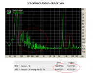
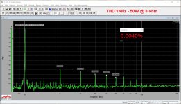
The graphs are generated by inputting a frequency tone (THD test) or a series of them (IMD test) and recording the voltages (sound) of the output. When a single 1KHZ tone is used for input, we look for its harmonics (noise reverberations) in the higher frequencies. The spikes you see in the graph are the measurements of these tone reverberations. A 1KHz tone input will have reverberations at 2KHz, 3KHz, 4KHz, 5KHz, etc. The level elevations of these spikes are essentially distortions of the original input so flatter is generally better. When we say even order harmonics in this example, we are describing the 2KHz and 4KHz reverberations and all their geometric multiples (8x, 16x, 32x, etc.), conversely, the odd order harmonics are all the other reverberations including the 6th and its multiples. Odd order harmonics are also called high order harmonics to make this point. It should be noted that an elevated 3rd harmonic (even when accompanied with some 5th) is not sonically objectionable when the 2nd and 4th are sufficiently suppressed in comparison. Amps with these characteristics have a distinctly different sound 'color' which some kinds of music expose. If you have some music background you will understand why this is so. In addition to the sonic character of the amp, the charts show us how quiet the amp is likely to be. The dB levels are usually expressed on the "Y" axis. Our esteemed member thimios highlights some aspects of his measurements in the second chart from the left on first line in post #362. You will note the nearly 800ppm of his full spectrum IMD. This is >10x the distortion seen in the less challenging tests. I've read in this thread that a quieter power supply has not improved the noise levels on this amp so that indicates to me that the circuit either needs quieter parts or layout tweaks to get better numbers.
I'm in Brooklyn, we should think about starting a northeast audio club if one hasn't already been established. I may not be Valery but I think I can explain the graphs so everyone can understand them.
vzaichenko
I'll try and save you some time and explain the graphs in laymen terms. Please step in if you think I missed anything important.
still4given
The graphs are generated by inputting a frequency tone (THD test) or a series of them (IMD test) and recording the voltages (sound) of the output. When a single 1KHZ tone is used for input, we look for its harmonics (noise reverberations) in the higher frequencies. The spikes you see in the graph are the measurements of these tone reverberations. A 1KHz tone input will have reverberations at 2KHz, 3KHz, 4KHz, 5KHz, etc. The level elevations of these spikes are essentially distortions of the original input so flatter is generally better. When we say even order harmonics in this example, we are describing the 2KHz and 4KHz reverberations and all their geometric multiples (8x, 16x, 32x, etc.), conversely, the odd order harmonics are all the other reverberations including the 6th and its multiples. Odd order harmonics are also called high order harmonics to make this point. It should be noted that an elevated 3rd harmonic (even when accompanied with some 5th) is not sonically objectionable when the 2nd and 4th are sufficiently suppressed in comparison. Amps with these characteristics have a distinctly different sound 'color' which some kinds of music expose. If you have some music background you will understand why this is so. In addition to the sonic character of the amp, the charts show us how quiet the amp is likely to be. The dB levels are usually expressed on the "Y" axis. Our esteemed member thimios highlights some aspects of his measurements in the second chart from the left on first line in post #362. You will note the nearly 800ppm of his full spectrum IMD. This is >10x the distortion seen in the less challenging tests. I've read in this thread that a quieter power supply has not improved the noise levels on this amp so that indicates to me that the circuit either needs quieter parts or layout tweaks to get better numbers.
Last edited:
I will add one point, the ac line is a good reference point, zero in on the 50-100Hz band. Does not matter what test it is, it is always there, if you are running off the ac line, at these sensitive levels. You might be able to see the higher harmonics of 50Hz, .. 150, 200 ... Only isolation will hide ac line in the noise.
You can see the 100Hz peak which represents the 2nd harmonic of the ac line 50Hz, you can tell the test is done in Europe. I assume 100Hz is higher than the 50Hz as it probably cross couples in the wiring (magnetic and electric) better than the fundamental.
You can see the 100Hz peak which represents the 2nd harmonic of the ac line 50Hz, you can tell the test is done in Europe. I assume 100Hz is higher than the 50Hz as it probably cross couples in the wiring (magnetic and electric) better than the fundamental.
Last edited:
Nania, I would love to get together. Thanks for the clear explanations.
I believe the graphs # 2,4,6,8 in post 360 and 362, with info in red circles, is a commercial amp shown as a comparison to the amp being discussed in the thread.
I believe the graphs # 2,4,6,8 in post 360 and 362, with info in red circles, is a commercial amp shown as a comparison to the amp being discussed in the thread.
From a well designed amplifier we expect
High PSRR( power supply rejection ratio).(No hum ,nothing to see in 50 or 100hz area or at least lower to -100db)
High dynamic range.A big number indigate a good dynamic range
Low noise.A big negative number indicate a quiet amplifier
Low harmonic distortion.The lower the better
Low intermodulation distortion.The lower the better
Hi Jeff,
thanks for advise- have searched and read a bit and found the right button to
push. 😀
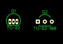
First convert to bmp or jpg and than a zip from idea what i do- should fit to
75mm high heat sink.
Your output devices should mount slightly below the center of the heat sink for best cooling.
Oh thanks for support.
If i find TO-92-100 it's clear much better- short view who other designt shows
the way. 😱
Not real center but different is second draft version.
The right way to change the pattern is to change the "attached pattern" in the schematic (right-click on the component). As soon as it's done for all the components you want to change - go to the layout and "Renew Layout from Schematic" (in File menu). All your changes will be reflected in the layout.
Keep the layout and the schematic linked all the time - this will ensure you have no errors in your layout. You can always compare your layout to schematic in Verification menu.
Understanding spectrums (FFT)
OK, my take on spectrums 😉
This kind of picture is a result of Fast Fourier Transform (FFT) - mathematical transformation of the input signal.
Fourier says - every input signal (whatever form it is) can be represented as a combination of sine waves.
Each "stick" on the spectrum diagram represents a single sine wave.
It is characterized by RMS Amplitude (V) and frequency (F).
Now - some explanation for each picture:
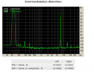
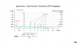
1) Typical FFT diagram. Base frequency component represents the test signal (1KHz sine wave) - set to 0db. A small (sometimes not so small 😛) stick on the left appears because of some PSU ripple (100Hz in Europe, 120Hz in US).
All the sticks on the right - harmonics of the base signal (F*2, F*3, F*4 and so on). It is noted that all the even components (2, 4, 6, etc.) are less audible (and more pleasing to some listeners) than the odd components (3, 5, 7, etc.).
Knowing the amplitude of each component, you can easily calculate the Total Harmonic Distortion (THD, db or %) at particular base frequency - see the formula at the bottom of the picture (measurement system makes this calculation automatically for you).
You can measure distortion at any base frequency - normally, it's 1KHz and 10KHz or 20KHz (if the sound card is used for measurements, for showing 20KHz harmonics adequately, it must be a good wide-band low-distortion sound card).
2) This is just to illustrate that an amplifier adds some components that are not in the input signal - this is what we hear as distortion. The output spectrum shown is not bad - 2-nd harmonic dominance, some 3-rd, all the rest are roughly at -100db and below.
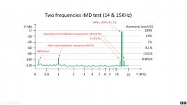
3) Another very important measurement - Inter-Modulation Distortion (IMD).
You send a mixture of two sine waves to the input - for example 14KHz and 15KHz (in this case each of them we normally set to -6db, then level of the mix will appear at 0db, as they sum up).
Passing through the amplifier, they inter-modulate each other, producing the addition (F2+F1) and subtraction (F2-F1) frequency components. I our case, (F2+F1) = 15 + 14 = 29KHz is not that interesting, but (F2-F1) = 15 - 14 = 1KHz is something we are really interested in. It's placed in the very audible frequency range and it was completely missing in the input signal - so we don't want to have it at the output.
In addition to that, secondary inter-modulation occurs, so we see F2+(F2-F1) and F1-(F2-F1) - and so on - components close to our F1 and F2 base signals'sticks.
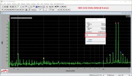
The real music signal consists of many components at the input - just imagine - they all inter-modulate each other and all the products of this inter-modulation inter-modulate each-other and so on. Horror 😱 Lots of new stuff, completely out of sync with the input signal. Good amplifier keeps the number and the level of these components relatively low. Here is an example of exceptionally low live-measured IMD: Vertical CFA + NS-OPS IMD. Evan - that's what you're enjoying right now 😀
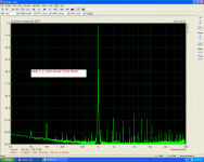
4) Example of IMD live measurement. You can clearly see 1KHz component, secondary components on the right, and - by the way - another small secondary component at 2KHz. Good amplifier.
5) Example of THD live measurement. Also a good one - 2-nd harmonic is dominant, 3-rd is half of it in amplitude (-6db), all the rest are below -100db level. Note some 100Hz recurring components between 1KHz and 2KHz - a little bit of PSU ripple, very low level though. Also note a small glitch at around 13KHz - that's a measurement system artifact.
These two spectrums above are taken on VHex+BT (Bi-Turbo double-bootstrap version).
This kind of diagrams (especially if they are available at different frequencies and amplitudes) allow seeing the amplifier's character - assessing not only harmonics' amplitudes, but also those amplitudes distribution (profile) and ratios between them.
I hope this is enough as a first introduction to FFT. Let me know is you will have questions 😉
Special thanks to all the other contributors on the topic - together, we show FFT under different angles.
Cheers,
Valery
OK, my take on spectrums 😉
This kind of picture is a result of Fast Fourier Transform (FFT) - mathematical transformation of the input signal.
Fourier says - every input signal (whatever form it is) can be represented as a combination of sine waves.
Each "stick" on the spectrum diagram represents a single sine wave.
It is characterized by RMS Amplitude (V) and frequency (F).
Now - some explanation for each picture:
1) Typical FFT diagram. Base frequency component represents the test signal (1KHz sine wave) - set to 0db. A small (sometimes not so small 😛) stick on the left appears because of some PSU ripple (100Hz in Europe, 120Hz in US).
All the sticks on the right - harmonics of the base signal (F*2, F*3, F*4 and so on). It is noted that all the even components (2, 4, 6, etc.) are less audible (and more pleasing to some listeners) than the odd components (3, 5, 7, etc.).
Knowing the amplitude of each component, you can easily calculate the Total Harmonic Distortion (THD, db or %) at particular base frequency - see the formula at the bottom of the picture (measurement system makes this calculation automatically for you).
You can measure distortion at any base frequency - normally, it's 1KHz and 10KHz or 20KHz (if the sound card is used for measurements, for showing 20KHz harmonics adequately, it must be a good wide-band low-distortion sound card).
2) This is just to illustrate that an amplifier adds some components that are not in the input signal - this is what we hear as distortion. The output spectrum shown is not bad - 2-nd harmonic dominance, some 3-rd, all the rest are roughly at -100db and below.
3) Another very important measurement - Inter-Modulation Distortion (IMD).
You send a mixture of two sine waves to the input - for example 14KHz and 15KHz (in this case each of them we normally set to -6db, then level of the mix will appear at 0db, as they sum up).
Passing through the amplifier, they inter-modulate each other, producing the addition (F2+F1) and subtraction (F2-F1) frequency components. I our case, (F2+F1) = 15 + 14 = 29KHz is not that interesting, but (F2-F1) = 15 - 14 = 1KHz is something we are really interested in. It's placed in the very audible frequency range and it was completely missing in the input signal - so we don't want to have it at the output.
In addition to that, secondary inter-modulation occurs, so we see F2+(F2-F1) and F1-(F2-F1) - and so on - components close to our F1 and F2 base signals'sticks.
The real music signal consists of many components at the input - just imagine - they all inter-modulate each other and all the products of this inter-modulation inter-modulate each-other and so on. Horror 😱 Lots of new stuff, completely out of sync with the input signal. Good amplifier keeps the number and the level of these components relatively low. Here is an example of exceptionally low live-measured IMD: Vertical CFA + NS-OPS IMD. Evan - that's what you're enjoying right now 😀
4) Example of IMD live measurement. You can clearly see 1KHz component, secondary components on the right, and - by the way - another small secondary component at 2KHz. Good amplifier.
5) Example of THD live measurement. Also a good one - 2-nd harmonic is dominant, 3-rd is half of it in amplitude (-6db), all the rest are below -100db level. Note some 100Hz recurring components between 1KHz and 2KHz - a little bit of PSU ripple, very low level though. Also note a small glitch at around 13KHz - that's a measurement system artifact.
These two spectrums above are taken on VHex+BT (Bi-Turbo double-bootstrap version).
This kind of diagrams (especially if they are available at different frequencies and amplitudes) allow seeing the amplifier's character - assessing not only harmonics' amplitudes, but also those amplitudes distribution (profile) and ratios between them.
I hope this is enough as a first introduction to FFT. Let me know is you will have questions 😉
Special thanks to all the other contributors on the topic - together, we show FFT under different angles.
Cheers,
Valery
Attachments

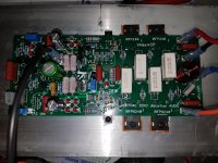
I've got a through hole VHex-CP amp running. Some scope shots and listening tests are coming soon.
Looks good. How does it sound?
Holidays are over so I will get started on in Monday. I only have one board etched so I need to make one more.
I have some more of the boards you sent that still need populating. Should have enough to keep me good through the month.
Blessings, Terry
- Home
- Amplifiers
- Solid State
- Sons of VHex