rhing said:
I soldered the wires for the AC and the output connections to the board connectors. For mechanical integrity in the board AC connections, I snipped off spades from some insulated crimp lugs and crimped the lug over the soldered connection. It's not the most elegant solution, but it worked for me. You can do this at your own risk.
I did something similar at the outputs.
I'm pretty amateur at soldering, so I was hoping for an easy connector solution. Haven't seen anything yet. I think I'll try the soldering.
Thanks!
Bob
Paul,
No I haven't worked out the earphone jack... I only know that when you unplug the connector to the headphone pcb, it stops the speaker output. I think the earphone jack has a switch at the back and it must disconnect the input signal when the jack's plugged into. That kinda sucks though... I don't like the idea of the input signal making the journey through all that wire. But, as I have said before... I really don't know that much about circuits.
I see what you mean about the led's in the input path... I wanted to use the leds as a source indicator, one for each input... but I guess I could just wire back to - at the power jack and use it as an on/off indicator. I noticed that some versions of the pcb just use a resistor and some also combine it with a capacitor. Would the capacitor help keep anything out of the signal path? Just wondering...
Eddie
Paul,
I looked at the earphone jack wiring and this is what I figured out.
The ear phone when plugged in switches the speaker out off and routes the signal to the pcb somewhere. When the earphone is not pugged in the circuit makes a loop ... I can check continuity back to tha caps I assume these are the + signals for each channel. I made a diagram of which wires are which...
I guess if you wanted to remove the whole connector you could do so and then just jump the connections from 6 to 8 and 7 to 9. That would remove a lot of wiring from the signal path.
See attached picture
Eddie
Attachments
erpii
Eddie, yes I looked at that circuit last nite & came up with the same answer as you. Accordingly I will shear off the ribbon @ the board & jumper pin's 6 & 8, 7 & 9, on the underneath of the board to keep it tidy.
You can still use your Led's as a source indicator for each input as you proposed, I would however sugest you run a seperate earth rail as distinct from using signal -.
If I had had more room I would have done the same with a rotary switch & the led's opposed by the degrees of rotation. No room in my $20 die cast case
Going to strip mine out tonite & hopefully get it off to the powder coater this week.
Trying to find a cutter I can sneak in to cut / crush R3, R02 is not so bad to get at. I will "blob" the 2 cap's.
With the 2 new Caps wired into the input, the circuit will then be identical to the Tripath evaluation board.
Hopefully I will have the case back & it up & running again in a couple of weeks.
Paul
Hi Paul...
So you will be soldering the input caps right at the junction of R3 R02?
Are you going to change any of the other caps?
About the leds... the way I see the circuit for the indicator led is that it is switched through the - signal. How would running another - line from, lets say, the input DC jack, be switched? Unless I had another pole on my switch, I don't see how it could be accomplished. How can I isolate it from the signal - and also switch it, without having another switch or pole on the switch I have? I guess I could put in a dedicated on/off switch and that would leave room on the source selector for the - led switching. If this can be accomplished lemme know. I don't know much about circuitry so I'm not doubting your proposal!
Thanks,
Eddie
Direct Comparison Between SI Gen 1 and Gen 2 T-Amps
I received a SI Gen 1 T-amp on loan and compared it to my SI Gen 2 T-amp.
Background:
I used Onix Reference 1 monitors (88dB efficient two-way monitors, 4Ohm nominal impedance), a modified Playstation 1 as a digital source and a Monster Interlink 200 RCA-to-3mm stereo jack adapter cable. I used each amp's respective stock power supplies (BI Switching Power Supply, 12VDC, 3A output) for the comparison. I also used a Skynet SNP-9037 switching power supply (SMPS) that used a Zu Cable Birth power cable and a DIY DC cable made of a twisted pair of 16AWG Teflon insulated Silver-plated Copper stranded conductors terminated with a Switchcraft 2.1mm/5.5mm DC connector. This happens to be an SMPS recommended by Michael Mardis. Unfortunately, for some reason, I could not power up the Gen 1 T-amp with the Skynet SMPS. I was able to swap the stock PSU's between amps (they are identical), but the Gen 1 wouldn't power up with the Skynet SMPS.
Conclusion:
I couldn't tell the difference between the T-amps. They both sounded identical at equal sound levels. I was expecting to hear lighter bass with the Gen 1 since many here have said that the Gen 2 has improved bass. When I first connected droht's Gen 1, I was surprised to hear the same sound quality as my Gen 2--the same level of bass was there. Now keep in mind that I do not have a subwoofer in my system, and the Ref 1's don't go really deep (approx. 55hz). It is possible that the Ref 1's just don't allow me to hear the difference in low frequency response. I might do measurements on my Gen 2 amp later this week when I have more time. I won't do any further testing with the Gen 1, because I don't want to risk damaging the loaner T-amp.
With the Gen 1, I had to turn up the volume knob from its starting position of 6 o'clock to 11 o'clock to get an equivalent loudness to the Gen 2 (from starting position of 7 o'clock to 10 o'clock). In other words, the volume pot on the Gen 2 seems to be more responsive in adjusting volume levels.
With the Skynet SMPS, the sound quality improved. The sound was less bright, much smoother and better balanced. The bass was tighter and more defined and low level detail came through more clearly. The soundstage became deeper. With the stock PSU in either amp, there is a very thin layer of grunge in the sound that I was only able to detect once i used the Skynet SMPS and then switched back to the stock PSU. Switching back and forth, I could really pick up on that layer of grunge. Another thing that was interesting was that I could hear up close a faint hum and low level hiss coming through the speakers with the amp sitting idle. I had both the Skynet and stock PSU's plugged into my power outlet bar with the Skynet actually powering the amp. When I unplugged the stock PSU, the hum and hiss disappeared.
I don't even use the stock PSU with my Gen 2 anymore. It's really disappointing that the Gen 1 didn't power up with the Skynet SMPS, because I am curious if the same improvements I've heard with the Gen 2 amp would carry over. The Switchcraft connector is a standard DC connector and should work with either amp. At this point, I would have to assume that if I could get the Gen 1 to work with the Skynet SMPS, the same improvements would occur.
I would recommend the Gen 2 T-amp over the Gen 1 T-amp based on the following:
1. The Gen 2 looks better IMHO and the blue LED illuminated volume knob is easier to adjust
2. The Gen 2 circuit board has a better layout for modifications. Also, it is bolted into the case rather than glued in with a hot melt adhesive
Other than those minor differences, they are both very good sounding amps in my system, and I would be happy to use either one. Now that I have this comparison out of the way, I'm going to start my Gen 2 T-amp upgrade project.
Attachments
Re: Direct Comparison Between SI Gen 1 and Gen 2 T-Amps
Thanks for taking the time to review both amps, it will help some potential buyers to decide. I have T-amp Gen 2, I too is quite please with it.
cheers.
rhing said:I received a SI Gen 1 T-amp on loan and compared it to my SI Gen 2 T-amp.
Background:
I used Onix Reference 1 monitors (88dB efficient two-way monitors, 4Ohm nominal impedance), a modified Playstation 1 as a digital source and a Monster Interlink 200 RCA-to-3mm stereo jack adapter cable. I used each amp's respective stock power supplies (BI Switching Power Supply, 12VDC, 3A output) for the comparison. I also used a Skynet SNP-9037 switching power supply (SMPS) that used a Zu Cable Birth power cable and a DIY DC cable made of a twisted pair of 16AWG Teflon insulated Silver-plated Copper stranded conductors terminated with a Switchcraft 2.1mm/5.5mm DC connector. This happens to be an SMPS recommended by Michael Mardis. Unfortunately, for some reason, I could not power up the Gen 1 T-amp with the Skynet SMPS. I was able to swap the stock PSU's between amps (they are identical), but the Gen 1 wouldn't power up with the Skynet SMPS.
Conclusion:
I couldn't tell the difference between the T-amps. They both sounded identical at equal sound levels. I was expecting to hear lighter bass with the Gen 1 since many here have said that the Gen 2 has improved bass. When I first connected droht's Gen 1, I was surprised to hear the same sound quality as my Gen 2--the same level of bass was there. Now keep in mind that I do not have a subwoofer in my system, and the Ref 1's don't go really deep (approx. 55hz). It is possible that the Ref 1's just don't allow me to hear the difference in low frequency response. I might do measurements on my Gen 2 amp later this week when I have more time. I won't do any further testing with the Gen 1, because I don't want to risk damaging the loaner T-amp.
With the Gen 1, I had to turn up the volume knob from its starting position of 6 o'clock to 11 o'clock to get an equivalent loudness to the Gen 2 (from starting position of 7 o'clock to 10 o'clock). In other words, the volume pot on the Gen 2 seems to be more responsive in adjusting volume levels.
With the Skynet SMPS, the sound quality improved. The sound was less bright, much smoother and better balanced. The bass was tighter and more defined and low level detail came through more clearly. The soundstage became deeper. With the stock PSU in either amp, there is a very thin layer of grunge in the sound that I was only able to detect once i used the Skynet SMPS and then switched back to the stock PSU. Switching back and forth, I could really pick up on that layer of grunge. Another thing that was interesting was that I could hear up close a faint hum and low level hiss coming through the speakers with the amp sitting idle. I had both the Skynet and stock PSU's plugged into my power outlet bar with the Skynet actually powering the amp. When I unplugged the stock PSU, the hum and hiss disappeared.
I don't even use the stock PSU with my Gen 2 anymore. It's really disappointing that the Gen 1 didn't power up with the Skynet SMPS, because I am curious if the same improvements I've heard with the Gen 2 amp would carry over. The Switchcraft connector is a standard DC connector and should work with either amp. At this point, I would have to assume that if I could get the Gen 1 to work with the Skynet SMPS, the same improvements would occur.
I would recommend the Gen 2 T-amp over the Gen 1 T-amp based on the following:
1. The Gen 2 looks better IMHO and the blue LED illuminated volume knob is easier to adjust
2. The Gen 2 circuit board has a better layout for modifications. Also, it is bolted into the case rather than glued in with a hot melt adhesive
Other than those minor differences, they are both very good sounding amps in my system, and I would be happy to use either one. Now that I have this comparison out of the way, I'm going to start my Gen 2 T-amp upgrade project.
Thanks for taking the time to review both amps, it will help some potential buyers to decide. I have T-amp Gen 2, I too is quite please with it.
cheers.
Nice review Rich! I may have to shell out for the Skynet PS. I've looked in cyber world, but haven't been able to locate one just yet. I may have to go to your source in the Bay area to have one shipped... is it located in Santa Clara?
So, you plan to mod the G2... Since I don't know what I'm doing, I guess I'll do the wait and see thing before starting to solder. If you don't mind me asking, what are your mod plans for the G2?
Ed
So, you plan to mod the G2... Since I don't know what I'm doing, I guess I'll do the wait and see thing before starting to solder. If you don't mind me asking, what are your mod plans for the G2?
Ed
erpiii
Eddie,
Re cap's, no my cap's are rather large being pp's. I will go into J2 from the Vol Pot sweeper after shielding the cap leads.
I will make up a "dummy" loom on an old Cap as the braid/heatshrink may make the wiring a bit stiff. I made a loom last nite for RCA's to Vol pot & it's OK because it's a lot longer & does not require acute bends.
The main board will be "floating" & only shielding connected to the die cast case. This worked well with my other T-Amps ( Sure & Charlize ) which are totally quiet.
Your Switch.
Had to go back to your drawing you put up a few post back. I assume you are going to use it as a power amp & bypass the Vol control. ?? as you have wired the RCA's directly to the amp input. Yes I should have looked closer at your drawing & looked at the Pot board also as the + & - pad's on the board are common for both Led's.
As you say you haven't enough poles & would need a seperate power switch & need to cut a trace on the board between the led's to do what I proposed.
Give it a go utilising a common -, after all Sonic do it that way & mine at least was very quiet, not totally but I think what noise I had was from my computer.
Are you re-casing it ??
Recd. 2 x more Sure boards today for next project. Have you tried them ?? They are very good with some basic Mod's & super cheap @ US$ 20.00 Plug & Play.
Paul
erpii
Eddie,
Where there''s a will there's a way.
Cuticle cutters can just get in to crush the resistors R02 & R3. Job done & circuit still intact less those beasties to earth.
Paul
Eddie,
Where there''s a will there's a way.
Cuticle cutters can just get in to crush the resistors R02 & R3. Job done & circuit still intact less those beasties to earth.
Paul
Paul,
I looked up the Sure boards... have you worked with them before? How do they sound? I see they have a 4 x 100 board... kinda like the 41hz.com basic 9 amp. Those amps a pretty cheap... and come assembled! Is this the site you get them from?
http://www.sureelectronics.net
Yes, I plan to re-box my G2... I'm going to start ordering the components tomorrow. Not sure what the final configuration will be at this time.
Eddie
Eddie
Sure boards. Yes you can order off that site or via Ebay.
I have built a couple up as well as 1 Charlize (www.diyparadise.com ). I will try & attach some photo's.
There are Forums on both the 15 & 100 Watt Sure amps here.
Of the lot I prefer the Charlize then the Sure & in last place the Sonic. Please bear in mind though the Sonic Mod's arent finished yet. The Sure's are modified which is very easy. The Charlize 2, is stock & sounds more like a tube amp, which I like. I would describe the Sure as haviing the qualities of both tube & solid state amps without being a compromise. Both of These amps have made me seriously cull my CD collection as they show up bad recordings big time.
I have a range of power supplies from SMPS, Laptop type, SMPS out of ATM Machine's, to a home brew ( round 35 years ago ) linear PS 30 amp continuous @ 13.8 Volts which I use for my ham radio gear.
The latter outperforms anything else I have tried though it weighs about 30 Lbs. It has a massive amount of high quality capacitance across the output.
For speakers I use Acoustic research from the early > Mid 80's & have various modell all restored.
In my shack here I use Pioneer 3 Ways & AR TSW 210's bookshelves for testing. All my speakers are 8 ohm & >87 db SPL.
I have no experience with the 41 Hz amp but now that Tripath has gone belly up, will probably build up a Gainclone in the near future.
Will try & attach some photos of finished amps. you can get Sure board photo's & Manual off their Ebay store. I can recomend them & they are good to deal with.
Paul
Sure boards. Yes you can order off that site or via Ebay.
I have built a couple up as well as 1 Charlize (www.diyparadise.com ). I will try & attach some photo's.
There are Forums on both the 15 & 100 Watt Sure amps here.
Of the lot I prefer the Charlize then the Sure & in last place the Sonic. Please bear in mind though the Sonic Mod's arent finished yet. The Sure's are modified which is very easy. The Charlize 2, is stock & sounds more like a tube amp, which I like. I would describe the Sure as haviing the qualities of both tube & solid state amps without being a compromise. Both of These amps have made me seriously cull my CD collection as they show up bad recordings big time.
I have a range of power supplies from SMPS, Laptop type, SMPS out of ATM Machine's, to a home brew ( round 35 years ago ) linear PS 30 amp continuous @ 13.8 Volts which I use for my ham radio gear.
The latter outperforms anything else I have tried though it weighs about 30 Lbs. It has a massive amount of high quality capacitance across the output.
For speakers I use Acoustic research from the early > Mid 80's & have various modell all restored.
In my shack here I use Pioneer 3 Ways & AR TSW 210's bookshelves for testing. All my speakers are 8 ohm & >87 db SPL.
I have no experience with the 41 Hz amp but now that Tripath has gone belly up, will probably build up a Gainclone in the near future.
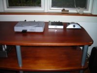
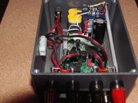
Will try & attach some photos of finished amps. you can get Sure board photo's & Manual off their Ebay store. I can recomend them & they are good to deal with.
Paul
Eddie
Sure boards. Yes you can order off that site or via Ebay.
I have built a couple up as well as 1 Charlize (www.diyparadise.com ). I will try & attach some photo's.
There are Forums on both the 15 & 100 Watt Sure amps here.
Of the lot I prefer the Charlize then the Sure & in last place the Sonic. Please bear in mind though the Sonic Mod's arent finished yet. The Sure's are modified which is very easy. The Charlize 2, is stock & sounds more like a tube amp, which I like. I would describe the Sure as haviing the qualities of both tube & solid state amps without being a compromise. Both of These amps have made me seriously cull my CD collection as they show up bad recordings big time.
I have a range of power supplies from SMPS, Laptop type, SMPS out of ATM Machine's, to a home brew ( round 35 years ago ) linear PS 30 amp continuous @ 13.8 Volts which I use for my ham radio gear.
The latter outperforms anything else I have tried though it weighs about 30 Lbs. It has a massive amount of high quality capacitance across the output.
For speakers I use Acoustic research from the early > Mid 80's & have various modell all restored.
In my shack here I use Pioneer 3 Ways & AR TSW 210's bookshelves for testing. All my speakers are 8 ohm & >87 db SPL.
I have no experience with the 41 Hz amp but now that Tripath has gone belly up, will probably build up a Gainclone in the near future.
Will try & attach some photos of finished amps. you can get Sure board photo's & Manual off their Ebay store. I can recomend them & they are good to deal with.
Paul
Sure boards. Yes you can order off that site or via Ebay.
I have built a couple up as well as 1 Charlize (www.diyparadise.com ). I will try & attach some photo's.
There are Forums on both the 15 & 100 Watt Sure amps here.
Of the lot I prefer the Charlize then the Sure & in last place the Sonic. Please bear in mind though the Sonic Mod's arent finished yet. The Sure's are modified which is very easy. The Charlize 2, is stock & sounds more like a tube amp, which I like. I would describe the Sure as haviing the qualities of both tube & solid state amps without being a compromise. Both of These amps have made me seriously cull my CD collection as they show up bad recordings big time.
I have a range of power supplies from SMPS, Laptop type, SMPS out of ATM Machine's, to a home brew ( round 35 years ago ) linear PS 30 amp continuous @ 13.8 Volts which I use for my ham radio gear.
The latter outperforms anything else I have tried though it weighs about 30 Lbs. It has a massive amount of high quality capacitance across the output.
For speakers I use Acoustic research from the early > Mid 80's & have various modell all restored.
In my shack here I use Pioneer 3 Ways & AR TSW 210's bookshelves for testing. All my speakers are 8 ohm & >87 db SPL.
I have no experience with the 41 Hz amp but now that Tripath has gone belly up, will probably build up a Gainclone in the near future.
Will try & attach some photos of finished amps. you can get Sure board photo's & Manual off their Ebay store. I can recomend them & they are good to deal with.
Paul
Circuit diagram
I bought the SI Gen 2 and I use it to drive the Tweeter/midrange, compression driver and horn combo, it sure gives a very different sound from the std linear amp like chipamp Lm3875. Actually I prefer the sound of the SI Gen 2 it adds a sparkle at the top.
I have the cct diagram from Gen 1 based on TA 2024.
Those here who are more informed and knowledgeable on this amp can please advise me on the following:
1. How different is version 2 differs from version 1? Can I use the cct diagram from version 1?
2. Can I change the gain of amp, how do I go about it?
thanks.
Thanks to all of you, I have had my SI Gen 2 up and running...nicely!
I have followed the instruction to the T and everything is working fine.
Not being an expert on electronics, but I managed to solder and crush those little "guys" without any problems.
I do have a question and am asking for guidance...
I would like to remove the blue light(s) from the original pot and mount it on my new case but not sure where to tap the wires to on the Gen2 board. Would you give me some instruction, please!
Again, thank you for all of your knowledge.
[I would like to remove the blue light(s) from the original pot and mount it on my new case but not sure where to tap the wires to on the Gen2 board. Would you give me some instruction, please!
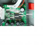
If you are using the original Pot/switch Board, you can simply remove the existing led's & replace 1 with a +/- lead to the new Led position. Remember the polarity, they wont work reverse polarity.
If using a new on/off switch, Pot etc best option is to use a 12 volt Bezel/Led combination, with built in dropping resistor & switch it from the new on off switch. I had a 1.7 volt led on my board & 2.4 volts on the rail accordingly the led lasted 30 minutes only. So with my exeperience, & I know of other blown led 's on Gen 2's, I would advise that route. Alternatively you can use the existing led & resistor off the pot board board wired back to the switch.
I will try & attach a photo so you can see what I did.
I powered mine off the B+/B- position & switched this line with the led connecteD to the switch. The "chocolate block" terminates all the - connections.
The Red/Black wires on J2 are simply jumpered.
Attachments
Thank you ZL2BPS for a quick reply and instruction.
I got “blue light” and the unit is singing beautifully. Now, all I have left to do is just breakin it in.
$60.00 for the SI Gen 2
+ $45.00 for the parts
+ the joy of a successful DIY (first time) project and the wonderful sound it delivers
= Priceless (until I make payment on my Master Card).
I got “blue light” and the unit is singing beautifully. Now, all I have left to do is just breakin it in.
$60.00 for the SI Gen 2
+ $45.00 for the parts
+ the joy of a successful DIY (first time) project and the wonderful sound it delivers
= Priceless (until I make payment on my Master Card).
has the T-amp from Sonic Impact been discontinued?.. Can't find the amp at their website and it's sold out at amazon.com, buy.com and thinkgeek.com..?
Parts Express has a spot to inform you by mail when they come in---according to their site, they expect them around the end of June.
Pete
Pete
- Status
- Not open for further replies.
- Home
- Amplifiers
- Class D
- Sonic Impact Gen 2 T-Amp ?