The Gen2 should drive them reasonably well, although at 90db, they arent going to shake the room. Also note that you wouldnt be able to directly hook up a powered sub to the amp. It can be done but requires additional equipment and setup.
amt
amt
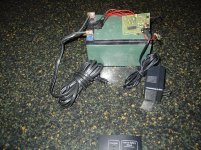
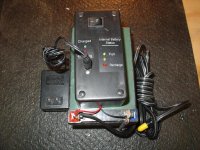
I have modded one of those 12 volt car jumper units which has a sealed lead acid batteries in it... just pulled everything out a resorted it. I plan on putting the charger in a box and then hooking it up to the battery. I can then recharge the battery when ever I need to. It also has an on off switch for the charger and leds for the charge and battery status. I had an old cord that powered from a car plug-in to the same size DC plug that's on the back of the amp... I just cut off the end and soldered some lugs and attached then to the battery. Not very pretty, but works very well. Now I'm portable!
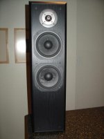
I've also modded some old speakers I had... I used some mid drivers from some Revel speakers I got. Swapped out some 5.5" for the 6.5 Revel drivers. It's got a lot more bass then the PSB Alpha B1's have. I think they sound very detailed and present an excellent sound stage. Still plan to tinker with the crossover top see
if they can sound even better. I sit on the floor to listen because I don't have any stands that are the right size for chair listening at this time.
I plan to do the mods when I confirm they work to everyones satisfaction.
ZL2BPS... Have you completed the new pot and caps mod yet? Do you have pictures?
Attachments

ZL2BPS... Have you completed the new pot and caps mod yet? Do you have pictures?
Well at the moment it's a sad story.
Got all the bit's together Friday nite to do the job & was working on the output end of the board cleaning out the speaker wire holes with a dremmel tool, ( I had removed these as they were C&*# wire I badly fitted) when 1 of my springer spaniels jumped up & knocked my arm.
End result some cut traces in the output & a torn off top L- pad. Now have a dead left channel & no audio on the right channel, I have a Headphone amp..
Put it away in disgust & will have to sit down & work out the output circuit in order to do the necessary repairs.
The frustrating thing is that I didn't really need to replace the output wires, they were just untidy..
As I have an eyesight problem, I will need to get some magnifying glasses B4 I try to repair. None of the SMD's seem damaged.
erpiii,
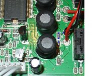
I have been looking at the above photo you posted & using it to get my board "älive" again. Have got the right channel back up but cannot see what I need to re-wire the left channel - connection.
Can you confirm that traces go to L - from FB1 & also from C50 please. This is the most damaged area on the board. Hopefully I can hard wire it & blob it with Epoxy.
Thanks
Has anyone else compared the sound of the gen 1 with the gen 2? Before doing any mods i wanted to know if anyone noticed or measured increased bass from the gen 2?
TIA,
Godzilla
TIA,
Godzilla
My understanding is that the Gen 2 has better bass.
I expect to have a chance to compare a stock Gen 2 to my own modified 1st gen in a week or two... I'll share my thoughts if/when that happens.
A
I expect to have a chance to compare a stock Gen 2 to my own modified 1st gen in a week or two... I'll share my thoughts if/when that happens.
A
ZL2BPS,
Sorry to hear about your mishap! Bad Dog!
I found continuity on both sides of FB1 and on one side of C50 from L-
See the picture for the spots I checked. Maybe the pic will help a bit!
Good luck!
Eddie
Sorry to hear about your mishap! Bad Dog!
I found continuity on both sides of FB1 and on one side of C50 from L-
See the picture for the spots I checked. Maybe the pic will help a bit!
Good luck!
Eddie
Dang it... what's so hard about attaching a picture...
ZL2BPS,
Sorry to hear about your mishap! Bad Dog!
I found continuity on both sides of FB1 and on one side of C50 from L-
See the picture for the spots I checked. Maybe the pic will help a bit!
Good luck!
Eddie
ZL2BPS,
Sorry to hear about your mishap! Bad Dog!
I found continuity on both sides of FB1 and on one side of C50 from L-
See the picture for the spots I checked. Maybe the pic will help a bit!
Good luck!
Eddie
Attachments
erpii.
"See the picture for the spots I checked. Maybe the pic will help a bit!"
Thanks Eddie, your photo confirms my though's on what should be there., once the dog's have gone to bed I will re wire the left channel & give it a whirl. If all is OK & we have liftoff, tomorrow night I will get on with the cap mod's. ( without the dog's helping.. )
Thanks again.
Eddie
Hard wired from the junction of FB1 & C50 to the L- output & it's going 100%.
For your info J2 connections are from Left to Right,
Red & black, the switched +power lead.
Right Channel Sweeper.
Common Ground left & right.
Left Sweeper.
Left Input.
Right input.
( the last 2 not being used when you use RCA's as you wire directly to the pot. )
Still have to work out the Headphone plug connections.
The new case I have is very small but will start the metalwork tomorrow as I need to mount the board to make sure I have room for the new cap's, Alps Pot, RCA's & Bananna plug's.
If I still have enough room I may consider keeping the headprone plug albeit that a 6.5mm plug would be better.
Hi everyone!
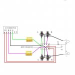
This is my plan for having 2 inputs using a 4PDT switch. The switch also functions as on/off and will light one of the two led's, depending on the source side of the switch. I'm just going to use the pcb for the led circuit and as a mounting platform for the led's. I Don't know if I've done this right or not... it looks logical to me. If anyone should see anything wrong please lemme know.
I have also bypassed the pot all together. My source (iPod) will be the volume control, as the levels I listen at are around mid volume on the iPod; my speakers being pretty efficient.
Another question... I've seen talk about removing the power protection diode and gaining a small amount of voltage by doing so... Anyone know if there is a power diode on the Gen 2? If so, where is it located? The only one I see is very small, located next to the chip between a small cap.
Any other news from anyone?
Thanks in advance!
Attachments
Just got a Skynet SNP-9037
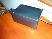
I recently purchased a Skynet SNP-9037 SMPS for my SI Gen 2 T-amp and installed it in a Radio Shack ABS case. The DC cable is a twisted pair of 18 AWG Teflon-insulated Silver-plated OFC with a TechFlex sleeve and terminated with a Switchcraft 2.1mm DC power connector. I will do some critical listening comparing this new SMPS and the stock SMPS.
I recently purchased a Skynet SNP-9037 SMPS for my SI Gen 2 T-amp and installed it in a Radio Shack ABS case. The DC cable is a twisted pair of 18 AWG Teflon-insulated Silver-plated OFC with a TechFlex sleeve and terminated with a Switchcraft 2.1mm DC power connector. I will do some critical listening comparing this new SMPS and the stock SMPS.
Attachments
Rich...
So, how much did the Skynet power supply cost? What is the amp rating on the ps?
Wouldn't it have been more cost effective to use a 12 sla battery as a power source? It's a little bigger but a pretty cheap alternative. I made one with a charger and it's quite convenient. I just press the on/off switch to charge at night or when I'm not listening.
erpiii said:Rich...
So, how much did the Skynet power supply cost? What is the amp rating on the ps?
Wouldn't it have been more cost effective to use a 12 sla battery as a power source? It's a little bigger but a pretty cheap alternative. I made one with a charger and it's quite convenient. I just press the on/off switch to charge at night or when I'm not listening.
I bought the Skynet SNP-9037 for $28 direct from American Skynet's operations in the San Franicsco Bay Area. Since I stopped by their offices and picked it up, I saved on shipping. It's a 12VDC/2.5A SMPS, and so far, it has made an improvement over the stock SI Gen 2 PSU. I really noticed the difference when I switched back to the stock PSU. The Skynet is cleaner and definitely smoother on peaks. When I checked the output, it consistenly locked in at 11.96VDC. The stock unit actually fluctuated at 12.10 +/- .25VDC.
I opted for a switch mode power supply over an SLA battery based on listening to a Red Wine Audio Reference 30 (Series 1) and some Zu Druids at RMAF 2006. It seemed like the amp would run out of headroom on peak transients. It didn't have that somewhat warm Tripath sound. Also, Michael Mardis has recommended this same SMPS.
I just received an SI Gen 1 T-amp on loan, so I'll be able to make direct comparisons between stock Gen 1 and Gen 2 T-amps. This should be interesting.
Attachments

rhing said:
I bought the Skynet SNP-9037...
I also bought one of these, but I haven't been able to figure out how to make the power connections. Can you tell me what connectors you used for both AC & DC sides?
Thanks,
Bob
erpii.
Eddie
Your Circuit looks OK & whilst I realise SI do it that way, I would not tie the diode - line to the signal - line. I would take the - line back to the input plug.
My understanding is that diodes introduce a degree of noise but am not sure regarding led's. Perhaps someone more technical can comment.
I have finished my metalwork & it's off to the powdercoater this week. While it's away I will snip & blob the redundant components.
Have you worked out the wiring for the headphone cable ??
Paul
rbclark said:
I also bought one of these, but I haven't been able to figure out how to make the power connections. Can you tell me what connectors you used for both AC & DC sides?
Thanks,
Bob
Refer to this data sheet for the connections:
http://www.skynetusa.com/images/stories/Series_Spec/snp-903%20series.pdf
I soldered the wires for the AC and the output connections to the board connectors. For mechanical integrity in the board AC connections, I snipped off spades from some insulated crimp lugs and crimped the lug over the soldered connection. It's not the most elegant solution, but it worked for me. You can do this at your own risk.
I did something similar at the outputs.
- Status
- Not open for further replies.
- Home
- Amplifiers
- Class D
- Sonic Impact Gen 2 T-Amp ?