I started a new thread on the DAO SE here :
http://www.diyaudio.com/forums/head...se-all-fet-class-zgf-headphone-amplifier.html
Patrick
http://www.diyaudio.com/forums/head...se-all-fet-class-zgf-headphone-amplifier.html
Patrick
again
inverted source follower:
I would like only remain that it
has good linearity,
high input impedance,
~270mA bias,
negative thermal coefficient for fets
and is so simply...
do you know other followers running @swing 30V with distortion ~-150dB?
inverted source follower:
I would like only remain that it
has good linearity,
high input impedance,
~270mA bias,
negative thermal coefficient for fets
and is so simply...
do you know other followers running @swing 30V with distortion ~-150dB?
Attachments

Last edited:

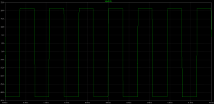
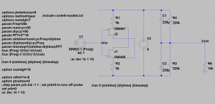
Not sure if im doing sthg wrong but i tried to sim using your asc file and get strange results .... see attached pic ...
😱
did you have and use cordell-models.txt like attached?
Attachments
yeap...i got mine off his webpage I'll try using the one you uploaded instead..
wait,
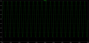
today I got this without the changes in asc...
I do not understand...😕
will keep you informed about the mistakes🙄
Attachments
The explanation:
in post 422 I clicked directly V1 voltage source...
and that was the reason of amazing low thd result...
in real life this circuit has positive feedback and act like voltage amp, not clear follower
do not send me to for this😉
in post 422 I clicked directly V1 voltage source...
and that was the reason of amazing low thd result...
in real life this circuit has positive feedback and act like voltage amp, not clear follower
do not send me to
for this😉> in real life this circuit has positive feedback and act like voltage amp, not clear follower
Glad you found out for yourself. 🙂
Patrick
Glad you found out for yourself. 🙂
Patrick
this time I have checked
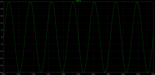
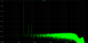
this is clear inverted follower with voltage sources instead of big caps at the input to let ltspice make good calculations/simulation.
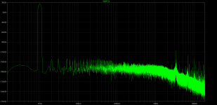
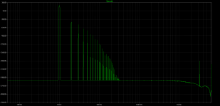
thd:
N-Period=1
Fourier components of V(vout)
DC component:0.0260207
Harmonic Frequency Fourier Normalized Phase Normalized
Number [Hz] Component Component [degree] Phase [deg]
1 1.000e+03 1.447e+01 1.000e+00 -0.01° 0.00°
2 2.000e+03 1.492e-02 1.031e-03 -92.14° -92.12°
3 3.000e+03 5.350e-03 3.697e-04 9.32° 9.33°
4 4.000e+03 8.804e-04 6.084e-05 80.75° 80.76°
5 5.000e+03 4.018e-04 2.777e-05 -149.71° -149.69°
6 6.000e+03 8.482e-05 5.862e-06 -113.99° -113.98°
7 7.000e+03 5.179e-05 3.579e-06 52.64° 52.66°
8 8.000e+03 1.114e-05 7.698e-07 46.49° 46.50°
9 9.000e+03 7.858e-06 5.431e-07 -115.42° -115.40°
Total Harmonic Distortion: 0.109745%
this is clear inverted follower with voltage sources instead of big caps at the input to let ltspice make good calculations/simulation.
thd:
N-Period=1
Fourier components of V(vout)
DC component:0.0260207
Harmonic Frequency Fourier Normalized Phase Normalized
Number [Hz] Component Component [degree] Phase [deg]
1 1.000e+03 1.447e+01 1.000e+00 -0.01° 0.00°
2 2.000e+03 1.492e-02 1.031e-03 -92.14° -92.12°
3 3.000e+03 5.350e-03 3.697e-04 9.32° 9.33°
4 4.000e+03 8.804e-04 6.084e-05 80.75° 80.76°
5 5.000e+03 4.018e-04 2.777e-05 -149.71° -149.69°
6 6.000e+03 8.482e-05 5.862e-06 -113.99° -113.98°
7 7.000e+03 5.179e-05 3.579e-06 52.64° 52.66°
8 8.000e+03 1.114e-05 7.698e-07 46.49° 46.50°
9 9.000e+03 7.858e-06 5.431e-07 -115.42° -115.40°
Total Harmonic Distortion: 0.109745%
Attachments
guitar/line buffer
Hi
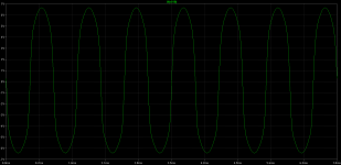
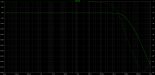
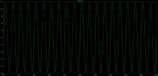
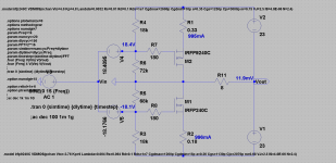
this time I have the idea of small signal pp source follower buffer with floating power supply.
the results are for 1Vpp at the input, the load is 10k.
for guitar the loads are much higher, 220k-10Meg which means lower distortion.
the circuit is easy for mounting inside the guitar together with the battery.
remember about hf blocking circuits.
Hi
this time I have the idea of small signal pp source follower buffer with floating power supply.
the results are for 1Vpp at the input, the load is 10k.
for guitar the loads are much higher, 220k-10Meg which means lower distortion.
the circuit is easy for mounting inside the guitar together with the battery.
remember about hf blocking circuits.
Attachments
Looking at the schematic aboev - how does this circuit work ?? The output looks like it is just DC
inv foll
Hi
this is just inverted source follower with dc path through.
you may just use 10k pot instead of one resistor to regulate 0 V dc at the output😉
Looking at the schematic aboev - how does this circuit work ?? The output looks like it is just DC
Hi
this is just inverted source follower with dc path through.
you may just use 10k pot instead of one resistor to regulate 0 V dc at the output😉
What is the current gain of this circuit. I could run a wire thru some passive components with no current gain and have nearly zero distortion.
not exactly
the circuit from post 430 is working good
from post 431 looks like J1 and 2 are not active dedices...
the circuit from post 430 is working good
from post 431 looks like J1 and 2 are not active dedices...
What do you think about using a cascaded Jfet like 370/170/309 on the output of a tube preamp? I have been thinking of good cascode devices. The 2sk2013 states 180V as its upper limit, but being a 25w part and being that it would not dissipate re than maybe 1w, I wonder if it is still usable. Any other devices you may suggest?
- Home
- Amplifiers
- Pass Labs
- Some other Source Follower Configurations