No problem at all, I really do understand - I started a amp pcb layout for a group on another forum last November, and have only just finished it.
With this hobby patience is perhaps the most important 'skill' to possess.
Thanks for the update.
With this hobby patience is perhaps the most important 'skill' to possess.
Thanks for the update.
Yes. As much fun as DIY Audio brings, work and family still come first.
And rightly so.
Patrick
And rightly so.
Patrick
this is my proposition: http://www.diyaudio.com/forums/pass-labs/215958-ticle-zen-amp-2.html
for a working circuit r5,6 should be changed to vbe multiplier or diode connected to the heatsik
for a working circuit r5,6 should be changed to vbe multiplier or diode connected to the heatsik
Patrick,
Got some great news....my DAO sounds gorgeous !!!😀😀😀
I've been working on it for ages..on and off, wanted to make it as a present for my son.
Yesterday finally fired it up...tested one channel, adjusted dc offset...no surprises but need to build other boards with better matching of transistors !
Even so when i put it all together today and listened on my 😱 noise canceling travel sennheisers 😱 i was blown away by the ease of presentation, resolution and as i had read...not tiring at all.
It's a privilege to hear music like this.
'course now i'll have to get a decent pair of ear muffs.😎
Thank you Patrick for this really very very good amp.
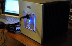
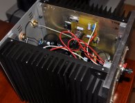
Some pictures...built arround some heatsinks i recycled...maybe too big but looks ok.
Thanks Steen for the inspiration .
It does get slightly above warm !
Got some great news....my DAO sounds gorgeous !!!😀😀😀
I've been working on it for ages..on and off, wanted to make it as a present for my son.
Yesterday finally fired it up...tested one channel, adjusted dc offset...no surprises but need to build other boards with better matching of transistors !
Even so when i put it all together today and listened on my 😱 noise canceling travel sennheisers 😱 i was blown away by the ease of presentation, resolution and as i had read...not tiring at all.
It's a privilege to hear music like this.
'course now i'll have to get a decent pair of ear muffs.😎
Thank you Patrick for this really very very good amp.
Some pictures...built arround some heatsinks i recycled...maybe too big but looks ok.
Thanks Steen for the inspiration .
It does get slightly above warm !
Attachments
Immaculate metal work.
Pity that you are too shy to show us the electronics inside as well. 🙂
Did you build the standard version or the Taylor current source ?
We should be ashamed.
We should have had finished our Beta test and release the PCBs by now.
Your work gives us impulse to renew our effort.
Thanks for sharing,
Patrick
I was wondering if the current was increased to about 1.5Amps like the F3, could the Aikido be coupled to this as the voltage gain stage? [+/- 18 volts, 1.5A pwr supply isn't a problem, could possibly use a servo to ensure 0V O/p]
In principle yes, but you need to change quite a few things if you are using the TCS.
For the standard version, just copy the cascoded cell around the LU1014 in the Zen V9.
If you draw the schematics I shall have a look for you.
Patrick
For the standard version, just copy the cascoded cell around the LU1014 in the Zen V9.
If you draw the schematics I shall have a look for you.
Patrick
Thanks Patrick
I'll have a look at it that way - looking for a way around the "active current source" technique (as per the F3), and was hoping to adapt your follower circuit to get the bigger current o/p drive.
I'll have a look at it that way - looking for a way around the "active current source" technique (as per the F3), and was hoping to adapt your follower circuit to get the bigger current o/p drive.
Immaculate metal work.
Pity that you are too shy to show us the electronics inside as well. 🙂
Did you build the standard version or the Taylor current source ?
We should be ashamed.
We should have had finished our Beta test and release the PCBs by now.
Your work gives us impulse to renew our effort.
Thanks for sharing,
Patrick
Thanks Patrick,
I was too busy enjoying the music to take the lid off again ...also wanted to see how temperature would stabilize with case closed.
After about 6 hours running time i can say it stabilizes pretty hot, no crickey hot ...but a fair bit above warm !
So in hind sight it's not too big, as a matter of fact it's just right.
I'm running it from CLC PSU with +-18V Toroid.
It's the TCS version and i use motorola 1N5314 instead of J511.
I had to fiddle around a bit with R1 to get Dc offset right because of bad matching.
I'll end up replacing the boards after decent matching new transistors and will probably go for your new boards as well in the process....but for now it sounds so good as is that i can do that relaxed with the knowledge that it's going to be even more outstanding 😀😉
I'll let you have a look at insides later this evening....
We'll try to finish testing the new boards before end of September so that we don't keep you all waiting too long.
My fault, as I keep interrupting with new circuit ideas.
Apologies for the exceedingl long wait,
Patrick
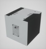
PS In our own case, we use a sink 200x250x37mm.
What size is your ? And how hot ?
My fault, as I keep interrupting with new circuit ideas.
Apologies for the exceedingl long wait,
Patrick
PS In our own case, we use a sink 200x250x37mm.
What size is your ? And how hot ?
😀😀😀
My case is 200 x200x200 ...hence DAO QB in face plate.
Heatsink is 4cm deep.
I did not measure temp yesterday but i would say it is somewhere in low 30ºCs....I'll get you precise numbers this evening.
PS: we all forgive you i think for always coming up with new circuit ideas...keep them coming 😀😎
My case is 200 x200x200 ...hence DAO QB in face plate.
Heatsink is 4cm deep.
I did not measure temp yesterday but i would say it is somewhere in low 30ºCs....I'll get you precise numbers this evening.
PS: we all forgive you i think for always coming up with new circuit ideas...keep them coming 😀😎
Attachments
Last edited:
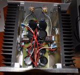
Ok Patrick...as promised ...some numbers and pictures.
Another 6 hours running and....in my son's room , no moving air, 20ish ambient temp:
Whole cube stabilizes at 41 ºC..with my lazer thermometer.
Took lid off ...measured the Panasonic 3W resistors...53 ºC, transitor case 46ºC ( not the JFETs , those are cooler ).
So i would say that this is pretty much worst case scenario and what is clear to me is that we should use parallel power resistors to lower individual temp but all else looks pretty good, case size and heat-sinks are optimum.
Any little air flow or lower ambient temp causes stabilized heat-sink temp in the region of the 30sºC.
I was listening in my living room with the windows open and that's what i got.
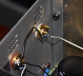
note:resistors in parallel with input are 10k !
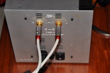
PS: wiring is a mess but it's early days, output and input, ground wires are silver from old coms equipment, power is run of the mill copper.
some pics:
Another 6 hours running and....in my son's room , no moving air, 20ish ambient temp:
Whole cube stabilizes at 41 ºC..with my lazer thermometer.
Took lid off ...measured the Panasonic 3W resistors...53 ºC, transitor case 46ºC ( not the JFETs , those are cooler ).
So i would say that this is pretty much worst case scenario and what is clear to me is that we should use parallel power resistors to lower individual temp but all else looks pretty good, case size and heat-sinks are optimum.
Any little air flow or lower ambient temp causes stabilized heat-sink temp in the region of the 30sºC.
I was listening in my living room with the windows open and that's what i got.
note:resistors in parallel with input are 10k !
PS: wiring is a mess but it's early days, output and input, ground wires are silver from old coms equipment, power is run of the mill copper.
some pics:
Attachments

Last edited:
I know that this may seem a bit ridiculous but when the fets run hot (heatsink temp, that is) they do sound better (IMO, naturally!) -at about 60*C is better - and still well within their SOA (Safe Operating Conditions).
Hi,
Thanks for the comments guys,
Well james , you are right ..that is how i run my F5 and it sound gorgeous.
We now have objective detailed numbers to fine tune, we can ;
0 - remember i measured temp in the evening at around 20ºC ambient temp...
1 - make smaller heatsinks or...
2 - crank up the bias a bit or...
3 - Leave as is because i want an all year amp and the weather in summer here in Lisbon is quite a bit above 30 ºC...sometimes above 40ºC.
As for the heatsinks...you are right also Patrick, my Chip amp ( Pavel Dudek's actually ) has an heatsink half the size of one of these....for both channels !
Since i happen to like the cube format, which happened by mere chance, i can take a cm of each side and be right on the magic formula.....but i don't think i will take that route....maybe next one.
😎
Last edited:
I did crank up the bias to about 350mA with my unit and it did seem to increase the dynamics and a better "timbre" (sorry about the vague terms) but the shunt reg (early version) couldn't handle it and I turned it back down to 250mA and left it there - meant to go back and try about 500mA but it sounds so good, it didn't happen!
I did rewire the k701s and that was a big improvement too.
You could try to block between the fins with material, or an outer cover, and get some increase in temp - not very "high tec" but works okay.
I did rewire the k701s and that was a big improvement too.
You could try to block between the fins with material, or an outer cover, and get some increase in temp - not very "high tec" but works okay.
..well there is another route for me james;
I'm using simple CLC PSU, if i move to Salas regs for each channel , just the heat from the shunt regs will drive overall temp up a bit.
Things to mull over while enjoying the music ....😀
I'm using simple CLC PSU, if i move to Salas regs for each channel , just the heat from the shunt regs will drive overall temp up a bit.
Things to mull over while enjoying the music ....😀
I know that this may seem a bit ridiculous but when the fets run hot (heatsink temp, that is) they do sound better (IMO, naturally!) -at about 60*C is better - and still well within their SOA (Safe Operating Conditions).
You have changed both the Tj and the output bias current.I did crank up the bias to about 350mA with my unit and it did seem to increase the dynamics and a better "timbre"
Can you repeat these experiments and change only one at a time and post your results?
It was awhile ago Andrew and I remember it quite clearly but I didn't do any distortion tests on it so no actual tech information, unfortunately -
when I increased the temp by adding the cover over the fins, the heatsink temp went up about 10*C and the sound became "clearer", a bit more "weight" in the bass, and a noticeable increase in the "grunt" (sorry about this babble!) but not much difference to the overall tonal balance of the sound - (ie the Gibson still sounded like a Gibson).
By increasing the current tho, the "detail" and "dynamics" increased without any increase in "hardness" - more like a first release pressing that the collectors go nuts for.
Sorry for the vague & loose descriptions
One thing I did do when I reverted to the 250mA current was to change out some of the PRP resistors (favourites) for some of those rather expensive Rhopoints and it definitely increased the detail, dynamics and surprising thing is that it seemed much more "analogue" - I think they call this a "darker" sound and that's as good a description as any (a bit hard to describe) - not a cheap exercise, but worth it, IMO.
Sorry I don't have anything concrete to add.
.....
One thing I did do when I reverted to the 250mA current was to change out some of the PRP resistors (favourites) for some of those rather expensive Rhopoints and it definitely increased the detail, dynamics and surprising thing is that it seemed much more "analogue" - I think they call this a "darker" sound and that's as good a description as any (a bit hard to describe) - not a cheap exercise, but worth it, IMO.
....
James, what specific resistors are you talking about ? i mean schematic ref...and rohpoints ? i go to rohpoint and all they have are caddocks...?
- Home
- Amplifiers
- Pass Labs
- Some other Source Follower Configurations