There is only one way to find out.
And you will not regret taking the trouble to find out.
😉
Patrick
And you will not regret taking the trouble to find out.
😉
Patrick
I wouldn't call this trouble; more like fun 🙂 I intend to build it as soon as I get the parts and will put it through the spectrum analyzer. No reason to expect disappointment.
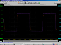
Remember to load it with low impedance (66 ohm or less).
I get perfect square waves with 67 ohm load.
(Magenta is input; orange is output under load.)
Patrick
I get perfect square waves with 67 ohm load.
(Magenta is input; orange is output under load.)
Patrick
Attachments
Last edited:
Definitely will test with load, since my interest is in an amp for my 63 ohm headphones.
Is that step response a real measurement?
Is that step response a real measurement?
No doubt you've explored this circuit a lot. Would replacing the lower jfet with a mosfet result in a significant performance drop? (Can you tell I'm cheap?)
If you use the standard DAO, then in theory you can use any constant current source. It so happens that the cascoded LU1014 is a very good one. But more importantly, I used them because they allow identical thermal drift on the upper and lower halves, thus guaranteeing near-zero DC offset. This is the same argument for using my 2SK372V heatsink for the current sourced loaded source follower, or the "B1".
In the TCS version, you are actually using the lower device as well to provide current. Thus the linearity of the lower device becomes equally important. And I certainly would not recommend you to use a mosfet there.
Patrick.
In the TCS version, you are actually using the lower device as well to provide current. Thus the linearity of the lower device becomes equally important. And I certainly would not recommend you to use a mosfet there.
Patrick.
You can either trim R1 (681R) or R2 (4.7R) to set the DC offset back to zero.
I would try 681R first as it is low power and high value.
Patrick
I would try 681R first as it is low power and high value.
Patrick
i m now listening to my newly transformed amp with grado sr225 and i noticed an increased in soundstaging and smoothness. since my source for now is only a modified x-fi and the 681r is a cheap trimpot, i cant comment any further than that.
also i use a clclclclclc composed of custom wound 15mh inductor and 10mf caps ( overkill? 🙂) as psu and the sound is much better than sigma22 except for bass and depth of scene.
thanks patrick for the help so far
also i use a clclclclclc composed of custom wound 15mh inductor and 10mf caps ( overkill? 🙂) as psu and the sound is much better than sigma22 except for bass and depth of scene.
thanks patrick for the help so far
Last edited:
Yes, it will work.
But no idea how it will affect the triode characteristics of the LU1014, as the transconductance is probably different at the bias current.
Patrick
But no idea how it will affect the triode characteristics of the LU1014, as the transconductance is probably different at the bias current.
Patrick
Hi EUVL,
I'm finishing my DAO build and i've just found an inconsistency between the schematic ( post 309 )and the PCBs of post 15 and 47...
The top ( in the schematic ) J511 connects to the +24v line but in all PCBs i've seen in this forum it connects directly to IRFP240 Drain.
Could you clear this up for me please ?
> The top ( in the schematic ) J511 connects to the +24v line but in all PCBs i've seen in this forum it connects directly to IRFP240 Drain.
There are very few who noticed that. 😉
In theory it is better to connect the current diode (J511) to the positive rail.
In that particular layout, it was a bit difficult, so I took the next best point that was more convenient for the layout, which was the drain of the cascode MOSFET. Because of the use of the current diode, this does not make much difference.
However, since the J511 is now obsolete, and you would probably want to use something like the E452 as a replacement, you can conveniently connect it back to the positive rail. In fact, this is what we are doing right now (in designing a proper PCB for the DAO TCS).
Patrick
Thanks Patrick,
I'm using 1N5314, but as you say it's easier for the layout to do it as you have done.
😉
I'm using 1N5314, but as you say it's easier for the layout to do it as you have done.
😉
...in designing a proper PCB for the DAO TCS.
More good news coming from Patrick. 😀
Can you get 1N5314 in Europe for reasonable price ?
Patrick
Got mine from a guy here in the forum.....😉
- Home
- Amplifiers
- Pass Labs
- Some other Source Follower Configurations